

Procedure, General Strain Relief Installation
Page
2
of
4
Document No
136505 Rev A
Form # 117140-D
5.4
Sealing the hole edges
CAUTION
: Cut edges can allow water and/or ice ingress and weaken the fiberglass laminate
or structural foam. It is essential to seal all cut edges thoroughly with fiberglass resin to
preserve the base pans structural strength.
CAUTION:
Fiberglass paste or RTV silicone sealant will not wick into and seal the fiberglass
strands as well as fiberglass resin, ONLY use fiberglass resin (such as TAP PLASTICS MARINE
VINYL ESTER, or equivalent) for sealing the cut edges.
Follow the manufacturer’s instructions to mix a small amount of fiberglass resin and catalyst,
then working quickly, use a disposable brush to apply mixed fiberglass resin to the hole edges,
both inside and out.
Allow the fiberglass resin to set per resin manufacturer’s instructions.
Note: Like all chemical reactions, set time will be temperature/humidity dependent.
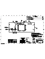
5.5
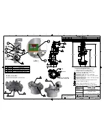
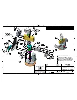
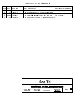
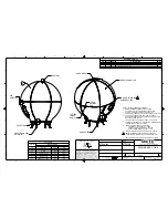
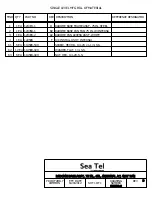
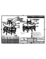
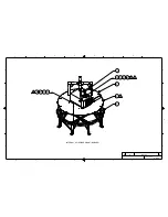
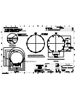
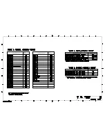
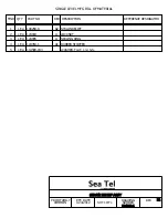
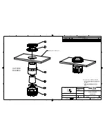
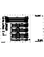
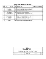
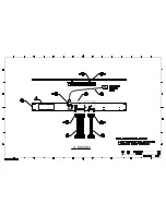
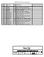
Refer to strain relief assembly draw ing 124903 (attached)
Being careful not to damage either the radome or the strain relief threads, use adjustable
pliers to install strain reliefs into the base pan with the locking nuts & sealing rings.
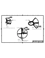
5.6
Installing Cables
Pass the end of the cable through the strain relief cap, washer, rubber stopper and then
trough the body of the strain relief into the radome interior.
Pull sufficient excess cable into the radome to route the cable to its intended termination
point. Once cables have been installed, slide the strain relief cap, washer and rubber stopper
up into the body of the strain relief.
Tighten the cap until the rubber compresses sufficiently to prevent the cable from sliding in
the body of the strain relief.
6.0
Records. N/A.
7.0
Training. N/A
8.0
References.
Strain relief assembly drawing (P/N: 124903)
Содержание 9711QOR-86
Страница 4: ......
Страница 13: ...Table of Contents xiii 23 1 9711QOR 86 MODEL SPECIFIC DRAWINGS 23 1 23 2 9711 GENERAL DRAWINGS 23 1 ...
Страница 14: ...Table of Contents xiv This Page Intentionally Left Blank ...
Страница 26: ...Site Survey 9711QOR 86 C Ku Band TXRX 2 8 This Page Intentionally Left Blank ...
Страница 70: ...Installation 9711QOR 86 C Ku Band TXRX 3 44 This Page Intentionally Left Blank ...
Страница 74: ...Basic Setup of the ACU 9711QOR 86 C Ku Band TXRX 4 4 This Page Intentionally Left Blank ...
Страница 78: ...Setup Ships Gyro Compass 9711QOR 86 C Ku Band TXRX 6 2 This Page Intentionally Left Blank ...
Страница 80: ...Setup Band Reflector Select 9711QOR 86 C Ku Band TXRX 7 2 This Page Intentionally Left Blank ...
Страница 86: ...Setup Home Flag Offset 9711QOR 86 C Ku Band TXRX 9 4 This Page Intentionally Left Blank ...
Страница 90: ...Setup Targeting 9711QOR 86 C Ku Band TXRX 10 4 This Page Intentionally Left Blank ...
Страница 96: ...Setup Searching 9711QOR 86 C Ku Band TXRX 11 6 This Page Intentionally Left Blank ...
Страница 122: ...Antenna Specific Operation 9711QOR 86 C Ku Band TXRX 16 12 This Page Intentionally Left Blank ...
Страница 126: ...Functional Testing 9711QOR 86 C Ku Band TXRX 17 4 This Page Intentionally Left Blank ...
Страница 142: ...Installation Troubleshooting 9711QOR 86 C Ku Band TXRX 18 16 This Page Intentionally Left Blank ...
Страница 188: ...9711QOR 86 Technical Specifications 9711QOR 86 C Ku Band TXRX 22 8 This Page Intentionally Left Blank ...
Страница 190: ...Drawings 9711QOR 86 C Ku Band TXRX 23 2 This Page Intentionally Left Blank ...
Страница 196: ......
Страница 199: ......
Страница 233: ......
Страница 234: ......
Страница 239: ......
Страница 241: ......
Страница 243: ......