


Installation
9711QOR-86 C & Ku-Band TXRX
3-40
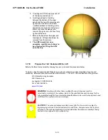
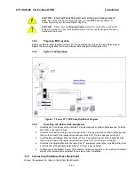
connected via a 9 pin ribbon cable to the ACU’s J2 NMEA communications port. A GPS
(Latitude and Longitude) input may also be connected, but is not required because there is
a GPS device already installed in your antenna.
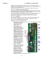
•
TxA- screw terminal is used to provide a Pseudo GPS (GGA and GLL formats) output to
other system components such as a Satellite Modem.
3.10.8.
Other BDE connections
Connect your other Below Decks Equipment (ie, telephone, fax machine and computer equipment) to
complete your configuration.
3.11.
Final Checks
3.11.1.
Visual/Electrical inspection
Do a visual inspection of your work to assure that everything is connected properly and all cables/wires are
secured.
3.11.2.
Electrical - Double check wiring connections
Double check all your connections to assure that it is safe to energize the equipment.
3.12.
Power-Up
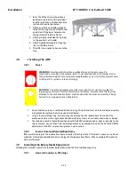
Verify that all shipping straps and restrains have been removed prior to energizing the antenna.
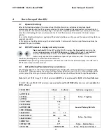
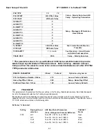
When all equipment has been installed, turn ACU Power and Antenna power ON. The ACU will initially sequentially
display:
“SEA TEL – MASTER and DAC-2202 VER 6.xx” followed by,
“SEA TEL – RCVR and SCPC VER 5.xx” followed by,
“SEA TEL – IO MOD and COMMIF VER 1.xx” followed by,
“SEA TEL – REMOTE and INITIALIZING”. After initialization, the bottom line of the remote display will display
the antenna model number and the software version from the PCU.
Energize and check the other Below Decks Equipment to verify that all the equipment is operating. You will need to
assure that the ACU is setup correctly and that the antenna acquires the correct satellite before you will be able to
completely check all the below decks equipment for proper operation.
3.13.
Cable Terminations
3.13.1.
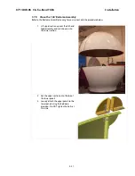
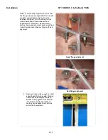
At The Radome
The TX and RX, or TVRO IF, cables must be inserted through the cable strain reliefs at the base of the radome.
Apply RTV to the strain relief joints and tighten the compression fittings to make them watertight. Attach the
pedestal cable adapters to the TX and RX, or TVRO IF, cables from below decks. Refer to the System Block
Diagram.
AC Power cable for the Antenna Pedestal and RF Equipment is routed into the AC Power Breaker box and
connected to the breaker terminals.
Sea Tel recommends that separate, dedicated, AC Power be provided for the Marine Air Conditioner (Do NOT
combine with the AC Power provided for the Antenna Pedestal and RF Equipment). This AC Power cable is
routed into the Marine Air Conditioner and terminated to the AC terminals inside.
3.13.2.
ACU & TMS
To Connect AC Power, Gyro Compass Connection and IF Input refer to the Antenna Control Unit manual.
Installation of optional (remote) Pedestal, and /or Radio, Monitor & Control connection(s) from a PC
Computer are also contained in the ACU manual.
3.13.3.
Other BDE Equipment
Refer to the vendor supplied manuals for installation of the other below decks equipment.
Содержание 9711QOR-86
Страница 4: ......
Страница 13: ...Table of Contents xiii 23 1 9711QOR 86 MODEL SPECIFIC DRAWINGS 23 1 23 2 9711 GENERAL DRAWINGS 23 1 ...
Страница 14: ...Table of Contents xiv This Page Intentionally Left Blank ...
Страница 26: ...Site Survey 9711QOR 86 C Ku Band TXRX 2 8 This Page Intentionally Left Blank ...
Страница 70: ...Installation 9711QOR 86 C Ku Band TXRX 3 44 This Page Intentionally Left Blank ...
Страница 74: ...Basic Setup of the ACU 9711QOR 86 C Ku Band TXRX 4 4 This Page Intentionally Left Blank ...
Страница 78: ...Setup Ships Gyro Compass 9711QOR 86 C Ku Band TXRX 6 2 This Page Intentionally Left Blank ...
Страница 80: ...Setup Band Reflector Select 9711QOR 86 C Ku Band TXRX 7 2 This Page Intentionally Left Blank ...
Страница 86: ...Setup Home Flag Offset 9711QOR 86 C Ku Band TXRX 9 4 This Page Intentionally Left Blank ...
Страница 90: ...Setup Targeting 9711QOR 86 C Ku Band TXRX 10 4 This Page Intentionally Left Blank ...
Страница 96: ...Setup Searching 9711QOR 86 C Ku Band TXRX 11 6 This Page Intentionally Left Blank ...
Страница 122: ...Antenna Specific Operation 9711QOR 86 C Ku Band TXRX 16 12 This Page Intentionally Left Blank ...
Страница 126: ...Functional Testing 9711QOR 86 C Ku Band TXRX 17 4 This Page Intentionally Left Blank ...
Страница 142: ...Installation Troubleshooting 9711QOR 86 C Ku Band TXRX 18 16 This Page Intentionally Left Blank ...
Страница 188: ...9711QOR 86 Technical Specifications 9711QOR 86 C Ku Band TXRX 22 8 This Page Intentionally Left Blank ...
Страница 190: ...Drawings 9711QOR 86 C Ku Band TXRX 23 2 This Page Intentionally Left Blank ...
Страница 196: ......
Страница 199: ......
Страница 233: ......
Страница 234: ......
Страница 239: ......
Страница 241: ......
Страница 243: ......