


9711QOR-86 C & Ku-Band TXRX
Installation
3-37
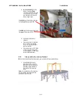
extension cable. Another choice is to connect the “ETHERNET” connector on the rear panel of the
ACU to a LAN connection on the computer or hub using an Ethernet crossover cable.
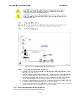
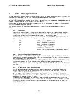
3.10.6.
Radio Control Serial Cable
If desired, connected the Radio Control Serial Cable from the Base Multiplexer to the COM Port of a
Customer Furnished Computer.
3.10.7.
Terminal Mounting Strip (TMS) Connections
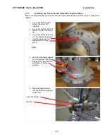
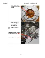
Connect the Ships Gyro Compass input to the appropriate screw terminals on this strip. The satellite modem
must also be connected to provide compliance with FCC Order 04-286 and WRC-03 Resolution 902.
There are several functional connections that may be made on the TMS connectors. Although you may not
need to make all of these connections, they are listed here for clarification during the installation process.
Connect the 9 pin ribbon cable from this PCB to J2 “NMEA” DB9 on the rear panel of the ACU. Connect the
25 pin ribbon cable from this PCB to J1 “Ship Gyro” DB25 on the rear panel of the ACU.
CAUTION - Electrical Shock Potentials exist on the Gyro Compass output
lines. Assure that the Gyro Compass output is turned OFF when handling
and connecting wiring to the Terminal Mounting Strip. DO NOT HOTPLUG
THIS CONNECTION
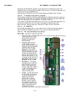
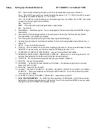
3.10.7.1.
Jumper Selection
JP1 – JP4 are used to couple in pull-up resistors for the below listed functions. JP5 selects the DC
voltage output on TS4.
JP1 SW1 – This output would be used for below decks Band Select - to control a band selection
switch or tone generator. Default is OPEN.
Shorted provides DC Voltage output (determined by JP5 setting) on the SW1 screw terminal to
supply voltage to a tone generator or band select switch.
Open provides continuity output (short to ground or open circuit) on the SW1 screw terminal to
control devices which have their own power source.
JP2 SW2 (blockage & RF radiation hazard output) - Provides TX Mute control to the Satellite
Modem for FCC compliance in all VSAT systems. It is also used to control antenna switching via a
dual antenna arbitrator in dual antenna configurations. Default is SHORTED when blocked. The
Blocked/Unblocked logic state can be reversed by including SYSTEM TYPE 0016.
Shorted provides DC Voltage output (determined by JP5 setting) on the SW2 screw terminal to
supply voltage to the satellite modem when the modem requires DC Voltage to Mute transmission.
In dual antenna configurations this used for dual antenna arbitrators that require DC Voltage to
switch. This hardware connection is also routed to the Console and OBM RJ45 ports.
Open provides continuity output (short to ground or open circuit) on the SW2 screw terminal to
satellite modem when the modem requires continuity control (short or open) to Mute transmission.
In dual antenna configurations this used for dual antenna arbitrators that require continuity control
(short or open) to switch. This hardware connection is also routed to the Console and OBM RJ45
ports.
JP3 SW3 (reserved) - Reserved for future use. Default is OPEN.
JP4 AGC (external AGC input) - Input from Satellite Modem which is used to provide a positive
satellite Network Lock (RX Sync) ID when the modem is on the correct network. Default is
SHORTED. The Locked/Unlocked logic state can be reversed by including SYSTEM TYPE 0128.
Shorted provides a pull-up DC Voltage input (determined by JP5 setting) into the ACU when the
modem supplies a continuity output. This hardware connection is also routed to the Console and
OBM RJ45 ports.
Open provides a DC Voltage directly from the modem into the ACU when the modem supplies a DC
Voltage output. This hardware connection is also routed to the Console and OBM RJ45 ports.
JP5 Voltage Output Select - Select 12VDC or 24VDC. Default is 12VDC.
JP6 GPS NMEA Output Select - Default is SHORTED.
Содержание 9711QOR-86
Страница 4: ......
Страница 13: ...Table of Contents xiii 23 1 9711QOR 86 MODEL SPECIFIC DRAWINGS 23 1 23 2 9711 GENERAL DRAWINGS 23 1 ...
Страница 14: ...Table of Contents xiv This Page Intentionally Left Blank ...
Страница 26: ...Site Survey 9711QOR 86 C Ku Band TXRX 2 8 This Page Intentionally Left Blank ...
Страница 70: ...Installation 9711QOR 86 C Ku Band TXRX 3 44 This Page Intentionally Left Blank ...
Страница 74: ...Basic Setup of the ACU 9711QOR 86 C Ku Band TXRX 4 4 This Page Intentionally Left Blank ...
Страница 78: ...Setup Ships Gyro Compass 9711QOR 86 C Ku Band TXRX 6 2 This Page Intentionally Left Blank ...
Страница 80: ...Setup Band Reflector Select 9711QOR 86 C Ku Band TXRX 7 2 This Page Intentionally Left Blank ...
Страница 86: ...Setup Home Flag Offset 9711QOR 86 C Ku Band TXRX 9 4 This Page Intentionally Left Blank ...
Страница 90: ...Setup Targeting 9711QOR 86 C Ku Band TXRX 10 4 This Page Intentionally Left Blank ...
Страница 96: ...Setup Searching 9711QOR 86 C Ku Band TXRX 11 6 This Page Intentionally Left Blank ...
Страница 122: ...Antenna Specific Operation 9711QOR 86 C Ku Band TXRX 16 12 This Page Intentionally Left Blank ...
Страница 126: ...Functional Testing 9711QOR 86 C Ku Band TXRX 17 4 This Page Intentionally Left Blank ...
Страница 142: ...Installation Troubleshooting 9711QOR 86 C Ku Band TXRX 18 16 This Page Intentionally Left Blank ...
Страница 188: ...9711QOR 86 Technical Specifications 9711QOR 86 C Ku Band TXRX 22 8 This Page Intentionally Left Blank ...
Страница 190: ...Drawings 9711QOR 86 C Ku Band TXRX 23 2 This Page Intentionally Left Blank ...
Страница 196: ......
Страница 199: ......
Страница 233: ......
Страница 234: ......
Страница 239: ......
Страница 241: ......
Страница 243: ......