Installation
9711QOR-86 C & Ku-Band TXRX
3-34
1.
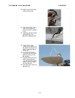
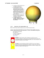
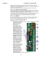
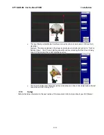
Enter the ADE and stow the antenna
pedestal using the Stow Kit (provided)
and the instruction in the Maintenance
section of the antenna manual.
2.
Attach eye-bolts or shackles (properly
rated for the weight to be lifted) to four
equidistant lifting point holes around
the perimeter of the Base Frame.
3.
Attach properly rated web lifting straps
to the eye-bolts, or shackles.
4.
Attach Appropriate length of rope tag
lines to the Base Frame.
5.
The ADE is now ready to hoist onto the
ship.
3.8.
Installing The ADE
3.8.1.
Hoist
WARNING:
Hoisting with other than a webbed four-part sling may result in
catastrophic crushing of the radome. Refer to the specifications and drawings for the
fully assembled weight of your model Antenna/Radome and assure that equipment used
to lift/hoist this system is rated accordingly.
CAUTION:
The antenna/radome assembly is very light for its size and is subject to
large swaying motions if hoisted under windy conditions. Always ensure that tag lines,
attached to the radome base frame, are attended while the antenna assembly is being
hoisted to its assigned location aboard ship.
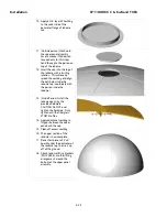
1.
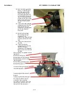
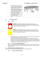
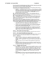
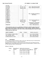
Assure that the antenna is restrained before hoisting. Check that all nuts on the base frame assembly
are tightened according the torque values listed below:
2.
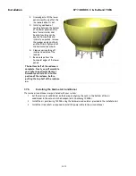
Using a four-part lifting sling, and with a tag line attached to the radome base frame, hoist the
antenna assembly to its assigned location aboard ship by means of a suitably-sized crane or derrick.
3.
The radome assembly should be positioned with the BOW marker aligned as close as possible to the
ship centerline. Any variation from actual alignment can be compensated with the AZIMUTH TRIM
adjustment in the ACU, so precise alignment is not required.
3.8.2.
Install Antenna/Radome/Baseframe
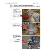
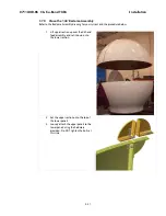
Bolt, or weld, the legs of the radome base frame directly to the ship's deck. If the deck is uneven or not level,
weld clips to the deck and attach them to the legs of the radome base frame. When completed the radome
base must be level.
3.9.
Installing the Below Decks Equipment.
Installing the Antenna Control Unit, Base Multiplexer Panel and the Terminal Mounting Strip.
3.9.1.
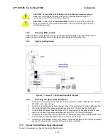
General Cautions & Warnings
Содержание 9711QOR-86
Страница 4: ......
Страница 13: ...Table of Contents xiii 23 1 9711QOR 86 MODEL SPECIFIC DRAWINGS 23 1 23 2 9711 GENERAL DRAWINGS 23 1 ...
Страница 14: ...Table of Contents xiv This Page Intentionally Left Blank ...
Страница 26: ...Site Survey 9711QOR 86 C Ku Band TXRX 2 8 This Page Intentionally Left Blank ...
Страница 70: ...Installation 9711QOR 86 C Ku Band TXRX 3 44 This Page Intentionally Left Blank ...
Страница 74: ...Basic Setup of the ACU 9711QOR 86 C Ku Band TXRX 4 4 This Page Intentionally Left Blank ...
Страница 78: ...Setup Ships Gyro Compass 9711QOR 86 C Ku Band TXRX 6 2 This Page Intentionally Left Blank ...
Страница 80: ...Setup Band Reflector Select 9711QOR 86 C Ku Band TXRX 7 2 This Page Intentionally Left Blank ...
Страница 86: ...Setup Home Flag Offset 9711QOR 86 C Ku Band TXRX 9 4 This Page Intentionally Left Blank ...
Страница 90: ...Setup Targeting 9711QOR 86 C Ku Band TXRX 10 4 This Page Intentionally Left Blank ...
Страница 96: ...Setup Searching 9711QOR 86 C Ku Band TXRX 11 6 This Page Intentionally Left Blank ...
Страница 122: ...Antenna Specific Operation 9711QOR 86 C Ku Band TXRX 16 12 This Page Intentionally Left Blank ...
Страница 126: ...Functional Testing 9711QOR 86 C Ku Band TXRX 17 4 This Page Intentionally Left Blank ...
Страница 142: ...Installation Troubleshooting 9711QOR 86 C Ku Band TXRX 18 16 This Page Intentionally Left Blank ...
Страница 188: ...9711QOR 86 Technical Specifications 9711QOR 86 C Ku Band TXRX 22 8 This Page Intentionally Left Blank ...
Страница 190: ...Drawings 9711QOR 86 C Ku Band TXRX 23 2 This Page Intentionally Left Blank ...
Страница 196: ......
Страница 199: ......
Страница 233: ......
Страница 234: ......
Страница 239: ......
Страница 241: ......
Страница 243: ......

