


9711QOR-86 C & Ku-Band TXRX
Setup – Tracking Receiver - VSAT
8-1
8.
Setup – Tracking Receiver - VSAT
8.1.
Determining the IF Tracking Frequency (MHz)
The IF Tracking frequency parameter is a value entered into the ACU’s MHZ Sub-Menu. The value itself may be
provided by your air-time provider and the MHz value will be entered directly in this sub-menu.
Or, the RF downlink frequency of a specific carrier on the desired satellite can be obtained from a satellite website and
calculated by using the formula RF- LO = IF. When you take the Satellite Transponder Downlink RF value and subtract
the LNB’s Local Oscillator (LO) Value, the resultant value will equal the Intermediate Frequency (IF). It is this IF value
that will be entered into the ACU for tracking purposes.
Example assuming an LNB LO value of 11.25GHz: 12268.0 MHz – 11250.0 MHz = 1018.0 MHz IF
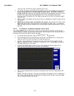
Identifying the Downlink RF using SatcoDX
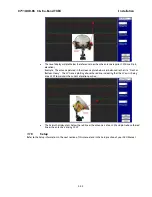
Identifying the Downlink RF using Capture from Lyngsat.com
8.2.
KHz
The KHz rate entered into the ACU is an absolute value which also may have been provided by your air-time provider,
or have been calculated, and is entered directly in this sub-menu window.
In the example above, 1018.0 MHz was calculated (1018 MHz 000 KHz) therefore, the KHz entry would be 000. If the
provided/calculated value had been 1018.250, 1018 would have been entered in the MHz window and 250 would be
entered in the KHz window.
8.3.
FEC
8.3.1.
L-Band SCPC Receiver
The Forward Error Correction rate entered into the ACU should always be set to SCPC with an L-Band SCPC
receiver card installed in the ACU.
8.4.
Tone
8.4.1.
VSAT Application
In VSAT antenna system, there is no need for below decks band selection and thus there is no applicable use
for tone control. For VSAT antenna systems that have voltage and tone controlled multiband LNB’s installed,
you will use the tracking band selection to control/toggle the tone state of a 22 KHz tone generator (installed
in the above decks equipment). For detailed information, refer to the “SETUP-Band Select” section of this
document.
Содержание 9711QOR-86
Страница 4: ......
Страница 13: ...Table of Contents xiii 23 1 9711QOR 86 MODEL SPECIFIC DRAWINGS 23 1 23 2 9711 GENERAL DRAWINGS 23 1 ...
Страница 14: ...Table of Contents xiv This Page Intentionally Left Blank ...
Страница 26: ...Site Survey 9711QOR 86 C Ku Band TXRX 2 8 This Page Intentionally Left Blank ...
Страница 70: ...Installation 9711QOR 86 C Ku Band TXRX 3 44 This Page Intentionally Left Blank ...
Страница 74: ...Basic Setup of the ACU 9711QOR 86 C Ku Band TXRX 4 4 This Page Intentionally Left Blank ...
Страница 78: ...Setup Ships Gyro Compass 9711QOR 86 C Ku Band TXRX 6 2 This Page Intentionally Left Blank ...
Страница 80: ...Setup Band Reflector Select 9711QOR 86 C Ku Band TXRX 7 2 This Page Intentionally Left Blank ...
Страница 86: ...Setup Home Flag Offset 9711QOR 86 C Ku Band TXRX 9 4 This Page Intentionally Left Blank ...
Страница 90: ...Setup Targeting 9711QOR 86 C Ku Band TXRX 10 4 This Page Intentionally Left Blank ...
Страница 96: ...Setup Searching 9711QOR 86 C Ku Band TXRX 11 6 This Page Intentionally Left Blank ...
Страница 122: ...Antenna Specific Operation 9711QOR 86 C Ku Band TXRX 16 12 This Page Intentionally Left Blank ...
Страница 126: ...Functional Testing 9711QOR 86 C Ku Band TXRX 17 4 This Page Intentionally Left Blank ...
Страница 142: ...Installation Troubleshooting 9711QOR 86 C Ku Band TXRX 18 16 This Page Intentionally Left Blank ...
Страница 188: ...9711QOR 86 Technical Specifications 9711QOR 86 C Ku Band TXRX 22 8 This Page Intentionally Left Blank ...
Страница 190: ...Drawings 9711QOR 86 C Ku Band TXRX 23 2 This Page Intentionally Left Blank ...
Страница 196: ......
Страница 199: ......
Страница 233: ......
Страница 234: ......
Страница 239: ......
Страница 241: ......
Страница 243: ......