


9711QOR-86 C & Ku-Band TXRX
Setup – Modem Connections, Setup and Test
13-1
13.
Setup – Modem Connections, Setup and Test
In order to be compliant with FCC Order 04-286 and WRC-03 Resolution 902 the Satellite Modem MUST be connected to the
Antenna control Unit/Terminal Mounting Strip to provide TX Mute control functionality. The FCC/WARC requirements have
been adopted by ITU & ETSI for them to publish similar requirements. The current FCC/WARC requirements are:
•
Mute the Transmit output of the Satellite Modem used in TX/RX antenna configurations when the antenna is
positioned where people may be harmed by the transmit power emanating from the antenna (RF Radiation Hazard).
•
Mute the Transmit output of the Satellite Modem used in TX/RX antenna configurations when the antenna is
mispointed by 0.5 degrees, or more, and keep it muted until the antenna is within 0.2 degrees of peak pointing to the
satellite for a minimum of 5 seconds (FCC part 25.221 & 25.222 TX Mute requirement).
The connection will also provide External Modem Lock and GPS Latitude & Longitude.
The External Modem Lock output from a satellite modem into the ACU provides a positive Network ID input to the ACU when
the antenna is on the desired satellite. This input is NOT used for Tracking purposes, it is only used for satellite
identification to assure that the satellite which has been acquired is the correct satellite (else the ACU will resume searching).
The GPS output from the ACU provides the current ships Latitude & Longitude as an input to the satellite modem for mobile
mode operation.
All modems must be set for mobile operation and have hardware handshaking turned ON.
13.1.
Jumper Selection
JP1 – JP4 are used to couple in pull-up resistors for the below listed
functions. JP5 selects the DC voltage output on TS4.
JP1 SW1 – This output would be used for below decks Band Select -
to control a band selection switch or tone generator. Default is
OPEN.
Shorted provides DC Voltage output (determined by JP5 setting) on the
SW1 screw terminal to supply voltage to a tone generator or band
select switch.
Open provides continuity output (short to ground or open circuit) on
the SW1 screw terminal to control devices which have their own power
source.
JP2 SW2 (blockage & RF radiation hazard output) - Provides TX
Mute control to the Satellite Modem for FCC compliance in all VSAT
systems. It is also used to control antenna switching via a dual antenna
arbitrator in dual antenna configurations. Default is SHORTED when
blocked. The Blocked/Unblocked logic state can be reversed by
including SYSTEM TYPE 0016.
Shorted provides DC Voltage output (determined by JP5 setting) on the
SW2 screw terminal to supply voltage to the satellite modem when the
modem requires DC Voltage to Mute transmission. In dual antenna
configurations this used for dual antenna arbitrators that require DC
Voltage to switch. This hardware connection is also routed to the
Console and OBM RJ45 ports.
Open provides continuity output (short to ground or open circuit) on
the SW2 screw terminal to satellite modem when the modem requires
continuity control (short or open) to Mute transmission. In dual
antenna configurations this used for dual antenna arbitrators that
require continuity control (short or open) to switch. This hardware
connection is also routed to the Console and OBM RJ45 ports.
JP3 SW3 (reserved) - Reserved for future use. Default is OPEN.
JP4 AGC (external AGC input) - Input from Satellite Modem which is used to provide a positive satellite Network
Lock (RX Sync) ID when the modem is on the correct network. Default is SHORTED. The Locked/Unlocked logic
state can be reversed by including SYSTEM TYPE 0128.
Содержание 9711QOR-86
Страница 4: ......
Страница 13: ...Table of Contents xiii 23 1 9711QOR 86 MODEL SPECIFIC DRAWINGS 23 1 23 2 9711 GENERAL DRAWINGS 23 1 ...
Страница 14: ...Table of Contents xiv This Page Intentionally Left Blank ...
Страница 26: ...Site Survey 9711QOR 86 C Ku Band TXRX 2 8 This Page Intentionally Left Blank ...
Страница 70: ...Installation 9711QOR 86 C Ku Band TXRX 3 44 This Page Intentionally Left Blank ...
Страница 74: ...Basic Setup of the ACU 9711QOR 86 C Ku Band TXRX 4 4 This Page Intentionally Left Blank ...
Страница 78: ...Setup Ships Gyro Compass 9711QOR 86 C Ku Band TXRX 6 2 This Page Intentionally Left Blank ...
Страница 80: ...Setup Band Reflector Select 9711QOR 86 C Ku Band TXRX 7 2 This Page Intentionally Left Blank ...
Страница 86: ...Setup Home Flag Offset 9711QOR 86 C Ku Band TXRX 9 4 This Page Intentionally Left Blank ...
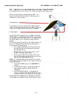
Страница 90: ...Setup Targeting 9711QOR 86 C Ku Band TXRX 10 4 This Page Intentionally Left Blank ...
Страница 96: ...Setup Searching 9711QOR 86 C Ku Band TXRX 11 6 This Page Intentionally Left Blank ...
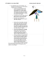
Страница 122: ...Antenna Specific Operation 9711QOR 86 C Ku Band TXRX 16 12 This Page Intentionally Left Blank ...
Страница 126: ...Functional Testing 9711QOR 86 C Ku Band TXRX 17 4 This Page Intentionally Left Blank ...
Страница 142: ...Installation Troubleshooting 9711QOR 86 C Ku Band TXRX 18 16 This Page Intentionally Left Blank ...
Страница 188: ...9711QOR 86 Technical Specifications 9711QOR 86 C Ku Band TXRX 22 8 This Page Intentionally Left Blank ...
Страница 190: ...Drawings 9711QOR 86 C Ku Band TXRX 23 2 This Page Intentionally Left Blank ...
Страница 196: ......
Страница 199: ......
Страница 233: ......
Страница 234: ......
Страница 239: ......
Страница 241: ......
Страница 243: ......