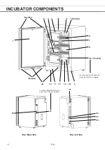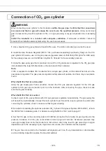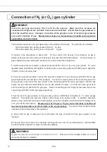
23. Connecting port A/B for N
2
/O
2
gas pipe:
Refer to page 17 for gas cylinder connection. Ensure that
the gas pressure is set at 0.05 MPaG (0.5 kgf/cm
2
G, 7.1 psiG). Refer to page 30 for automatic N
2
(or O
2
)
gas cylinder changeover.
24. Attachment location for electric key:
This is the attachment location for the electric key included in
the optional Component H
2
O
2
Decontamination Kit (MCO-HL). This kit must be attached to perform H
2
O
2
decontamination. Refer to the installation procedure for MCO-HL for details.
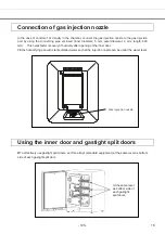
25. Gas injection nozzle
* MCO-19M(UVH)/19M(UV) or when an optional UV System Kit (MCO-19UVS) is installed.*
- 118 -
11
Содержание MCO-19M
Страница 7: ... 4 Dimensions Power cord ...
Страница 16: ...Wiring diagram 13 ...
Страница 17: ...Circuit diagram Main PCB 14 ...
Страница 18: ... LCD PCB 15 ...
Страница 110: ...MCO 19M UVH MCO 19M UV MCO 19M Multi Gas Incubator INSTRUCTION MANUAL 107 ...
Страница 112: ...CONTENTS SPECIFICATIONS P 74 PERFORMANCE P 75 SAFETY CHECK SHEET P 76 109 2 ...
Страница 183: ...Fig A Stacking plate B Stacking plate A Protective sticker Front panel Hook Front 180 73 ...
Страница 187: ...SANYO Electric Co Ltd Printed in Japan DC3186 150B ...

