Connection of CO
2
gas cylinder
WARNING
When connecting a gas cylinder to the Incubator,
confirm the gas type
.
Confirm that the connections
are secure and that no gas will escape
.
Be sure to use the specified pressure
. Using an incorrect
gas or pressure may result in explosion or fire, or in gas poisoning or oxygen deprivation due to escaping
gas.
Install the Incubator in a location with adequate ventilation.
If adequate ventilation cannot be
provided, then install an alarm system using
CO
2
and O
2
densitometers.
1.
Use a liquefied CO
2
gas cylinder (at least 99.5% pure). The siphon (dip tube) type cannot be used.
2.
Install the Gas Pressure Regulator (MCO-100L, purchased separately) specified by Sanyo on the CO
2
gas cylinder. Otherwise, use a CO
2
gas pressure regulator rated at 25 MPaG (250 kgf/cm
2
G, 3600 psiG)
for the primary pressure, and 0.2 MPaG (2 kgf/cm
2
G, 30 psiG) for the secondary pressure.
3.
Using the gas supply pipe that is provided, connect the CO
2
gas pressure regulator to the CO
2
gas pipe
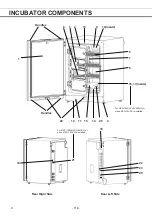
inlet (located at the lower left-hand side on the rear panel of the Incubator).
Note:
If CO
2
is supplied to multiple CO
2
Incubators from a single gas cylinder, a CO
2
solid will be formed in the
gas pressure regulator. The gas pressure regulator safety valve will operate, and there may an explosive
sound.
When the MCO-21GC is not mounted
Using the gas supply pipe that is provided, connect the CO
2
gas pressure regulator for the CO
2
gas
cylinder to CO
2
gas pipe connection port A on the Incubator. After connecting the pipe, check to make
sure that no gas is leaking.
When the MCO-21GC is mounted
Connect a pair of CO
2
gas cylinders with CO
2
gas pressure regulators independently. The gas supply line
will be switched automatically. Connect the main cylinder to port A and the reserve cylinder to port B. After
connecting the cylinders, check to make sure that no gas is leaking.
z
For details on installing the optional automatic CO
2
Cylinder Changeover System (MCO-21GC), refer to
the MCO-21GC installation guide. For details on using the MCO-21GC, refer to page 67.
4.
Set the CO
2
gas on the secondary side to 0.03 MPaG (0.3 kgf/cm
2
G, 4.3 psiG) for gas injection. As the
pressure increases, the CO
2
gas concentration control range will increase. Excessive pressure may
cause gas supply lines inside the Incubator to come loose, which may result in gas poisoning or oxygen
deprivation due to the escaping of gas. If gas lines come loose, the Incubator must be repaired.
z
The gas lines connected to the Incubator will degrade over time. If any deterioration or abnormalities
are found during inspection, replace the lines immediately.
- 123 -
16
Содержание MCO-19M
Страница 7: ... 4 Dimensions Power cord ...
Страница 16: ...Wiring diagram 13 ...
Страница 17: ...Circuit diagram Main PCB 14 ...
Страница 18: ... LCD PCB 15 ...
Страница 110: ...MCO 19M UVH MCO 19M UV MCO 19M Multi Gas Incubator INSTRUCTION MANUAL 107 ...
Страница 112: ...CONTENTS SPECIFICATIONS P 74 PERFORMANCE P 75 SAFETY CHECK SHEET P 76 109 2 ...
Страница 183: ...Fig A Stacking plate B Stacking plate A Protective sticker Front panel Hook Front 180 73 ...
Страница 187: ...SANYO Electric Co Ltd Printed in Japan DC3186 150B ...


