


- 82 -
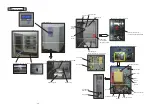
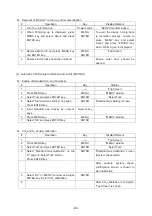
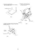
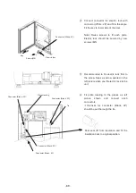
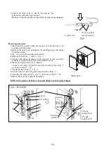
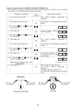
6. Fit the duct to original position.
Place the humidifying tray and set the humidifying
tray cover as shown in Fig. 5.
㻌
㻌
㻌
㻌
㻌
㻌
㻌
㻌
㻌
㻌
㻌
㻌
㻌
㻌
㻌
㻌
㻌
㻌
㻌
㻌
㻌
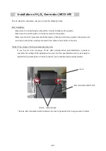
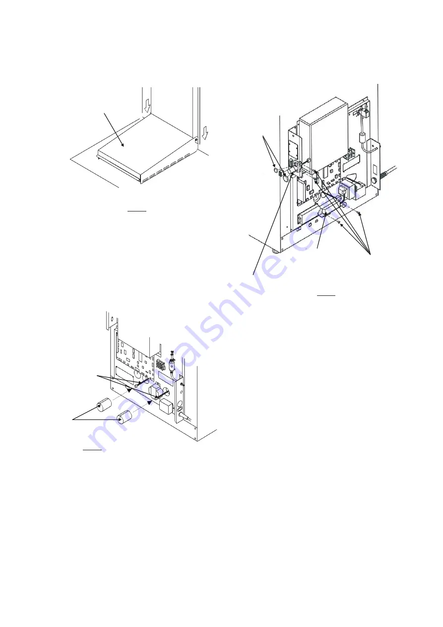
7. Replace the insulations into the UV lamp lead wire
hole with the wires passed through the cuts on both
insulations. See Fig. 6.
㻌
㻌
㻌
㻌
㻌
㻌
㻌
㻌
㻌
㻌
㻌
㻌
㻌
㻌
㻌
UV lamp
lead wire
Insulation
Fig. 6
Fig. 5
Humidifying tray cover
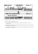
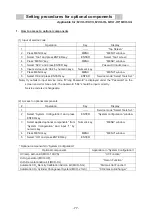
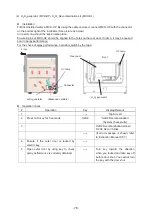
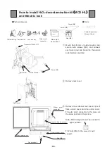
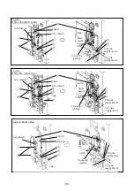
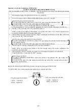
8. Remote the 2 caps shown in Fig. 7.
Fit Glow Ass’y (
䐢
) and Ballast (
䐣
)
by using 4 screws (
䐡
).
䐡
Screw (4pcs)
䐢
Glow Ass’y
Cap
䐣
Ballast
Fig. 7
Содержание MCO-19M
Страница 7: ... 4 Dimensions Power cord ...
Страница 16: ...Wiring diagram 13 ...
Страница 17: ...Circuit diagram Main PCB 14 ...
Страница 18: ... LCD PCB 15 ...
Страница 110: ...MCO 19M UVH MCO 19M UV MCO 19M Multi Gas Incubator INSTRUCTION MANUAL 107 ...
Страница 112: ...CONTENTS SPECIFICATIONS P 74 PERFORMANCE P 75 SAFETY CHECK SHEET P 76 109 2 ...
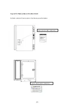
Страница 183: ...Fig A Stacking plate B Stacking plate A Protective sticker Front panel Hook Front 180 73 ...
Страница 187: ...SANYO Electric Co Ltd Printed in Japan DC3186 150B ...