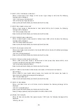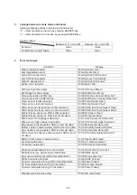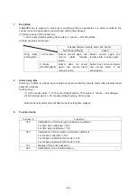
- 8 -
O
2
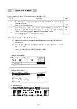
span calibration
(Ex
䠅
When setting O
2
density is 5.0% and actual O
2
density is 4.5%:
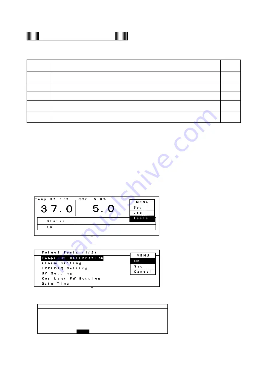
Process Operation MENU
1
Put densitometer thorough the sample port at the front side of the unit to measure
chamber O
2
density.
2
Select Tools in the Top Screen.
Tools
3
Select Tools (1/2) is displayed. Select temp / CO
2
Calibration and press OK key.
OK
4
By pressing digit shift key and numerical value shift key, input actual O
2
density
䠄
4.5%
䠅
in the column O
2
Span. Select OK and press ENTER key.
OK
5
Automatically reverts to Select Tools (1/2) screen.
*Note (1)
㻌
Input range: +1.0% ~ -1.0% (per input).
(2)
㻌
Repeat O2 calibration for several times until displayed CO2 density will match with
actual density.
(3)
㻌
It is unacceptable to commence O2 span calibration when setting O2 density deviates
㻌
䡂
rom 18.0 ~ 22.0
䠂
.
㻌 㻌 㻌
There is a blank in the rignt side of
䇾
O2 Span
䇿
column.
䠘
Display of Process-2
䠚
䠘
Display of Process-3
䠚
O
2
span calibration
䣖 䣧 䣯 䣲 䢱 䣅 䣑 䢴 䢱 䣑 䢴
䣅 䣣 䣮 䣫 䣤 䣴 䣣 䣶 䣫 䣱 䣰
䢪 䢳 䢱 䢴 䢫
䣒 䣘
䣘 䣱 䣮 䣶
䣖 䣧 䣯 䣲
䣕 䣲 䣣 䣰
䢲 䢰 䢲 䤑䣅
䢵 䢹 䢰 䢲 䤑䣅
䢲 䢰 䢷 䤑䣅
䣅 䣑 䢴
䣜 䣧 䣴 䣱
䢵 䢰 䢻 䢳
䣘
䢷 䢲 䢲
䣅 䣑 䢴
䣕 䣲 䣣 䣰
䢲 䢰 䢲 䢧
䢷 䢰 䢲 䢧
䢵 䢰 䢳 䢸
䣘
䢹 䢲 䢲
䣑 䢴
䣜 䣧 䣴 䣱
䢷 䢲 䢲
䣑 䢴
䣕 䣲 䣣 䣰
䢲 䢰 䢲
䢧
䢷 䢰 䢲 䢧
䢷 䢺
䣯 䣘
䢷 䢲 䢲
Содержание MCO-19M
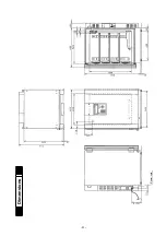
Страница 7: ... 4 Dimensions Power cord ...
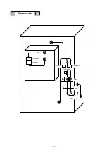
Страница 16: ...Wiring diagram 13 ...
Страница 17: ...Circuit diagram Main PCB 14 ...
Страница 18: ... LCD PCB 15 ...
Страница 110: ...MCO 19M UVH MCO 19M UV MCO 19M Multi Gas Incubator INSTRUCTION MANUAL 107 ...
Страница 112: ...CONTENTS SPECIFICATIONS P 74 PERFORMANCE P 75 SAFETY CHECK SHEET P 76 109 2 ...
Страница 183: ...Fig A Stacking plate B Stacking plate A Protective sticker Front panel Hook Front 180 73 ...
Страница 187: ...SANYO Electric Co Ltd Printed in Japan DC3186 150B ...

