- 16 -
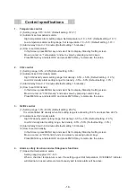
Control specifications
1. Temperature
control
(1) Setting range: 0.0
Υ
~50.0
Υ
(Default setting: 37.0
Υ
)
(2) Automatic set temperature alarm
High temperature alarm setting range: Set tempe1.0~+5.0
Υ
(Default s1.0
Υ
)
Low temperature alarm setting range: Set temperature -1.0~-5.0
Υ
(Default setting:-1.0
Υ
)
(3) Alarm delay time: 0~15 minutes (Default setting: 15 minutes)
(4) How to set temperature
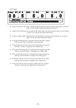
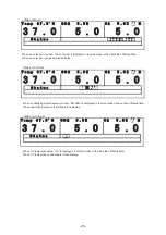
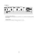
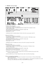
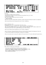
In TopScreen, press MENU key and select Set to display Stand-by Setting screen.
Move a curser on “Temperature” and set a value by pressing numeric keys.
Press MENU key and select OK and press ENTER key to memorize the value.
2. CO2
control
(1) Setting range: 0.0%~20.0%(Default setting: 0.0%)
(2) Automatic set CO2 density alarm
High CO2 density alarm setting range: Set d0.5%~+5.0% (Default setting: +1.0%)
Low CO2 density alarm setting range: Set density -0.5%~-5.0% (Default setting: -1.0%)
(3) Alarm delay time: 0~15 minutes (Default setting: 15 minutes)
(4) How to set CO2 density
In TopScreen, press MENU key and select Set to display Stand-by Setting screen.
Move a curser on “CO2 Density” and set a value by pressing numeric keys.
Press MENU key and select OK and press ENTER key to memorize the value.
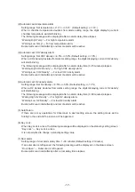
3. N2/O2
control
(1) Setting range: 1.0%~80.0% (Default setting: 20.0%)
It is uncontrolled O2 density when O2 setting range is exceeding 18.0% and less than 22.0%.
(2) Automatic set O2 density alarm
High O2 density alarm setting range: Set d0.5%~+5.0% (Default setting: +1.0%)
Low O2 density alarm setting range: Set density -0.5%~-5.0% (Default setting: -1.0%)
(3) Alarm delay time: 0~30 minutes (Default setting: 30 minutes)
(4) How to set O2 density
In TopScreen, press MENU key and select Set to display Stand-by Setting screen.
Move a curser on “O2 Density” and set a value by pressing numeric keys.
Press MENU key and select OK and press ENTER key to memorize the value.
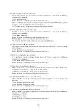
4.
Alarms, safety functions and self diagnosis functions
(1) Upper limit temperature alarm
Setting
range:
Approx.35
Υ
~51
Υ
When a chamber temperature is over the setting upper limit temperature, OVERHEAT indicator
will illuminate, buzzer will sound continuously and remote alarm will be active.
Содержание MCO-19M
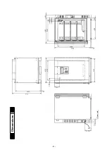
Страница 7: ... 4 Dimensions Power cord ...
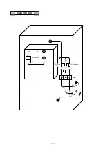
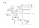
Страница 16: ...Wiring diagram 13 ...
Страница 17: ...Circuit diagram Main PCB 14 ...
Страница 18: ... LCD PCB 15 ...
Страница 110: ...MCO 19M UVH MCO 19M UV MCO 19M Multi Gas Incubator INSTRUCTION MANUAL 107 ...
Страница 112: ...CONTENTS SPECIFICATIONS P 74 PERFORMANCE P 75 SAFETY CHECK SHEET P 76 109 2 ...
Страница 183: ...Fig A Stacking plate B Stacking plate A Protective sticker Front panel Hook Front 180 73 ...
Страница 187: ...SANYO Electric Co Ltd Printed in Japan DC3186 150B ...

