- 53 -
㻌
㻌
㻌
10. Setting of various optional components
㻌
㻌
䣦 䣣 䣶 䣣
䣫 䣼 䣧
䣶 䣫 䣣 䣮
䣋 䣰 䣫
䣷 䣵
䣕 䣶 䣣 䣶
䣫 䣰 䣩
䣕 䣧 䣶 䣶
䣥 䣱 䣰
䣆 䣧
䣣 䣰 䣥 䣧
䣄 䣣 䣮
䣣 䣶 䣧 䣴
䣮
䣣 䣰 䣥 䣧
䣅
䣊 䣧
䣥
䣰
䣧 䣶
䣣 䣶 䣫 䣱
䣮 䣫 䣤 䣴
䣩
䣅 䣣
䣰 䣣 䣮 䣱
䣃
䣑 䣍
䣱 䣰
䣴 䣣 䣶 䣫
䣨 䣫 䣩 䣷
䣅 䣱 䣰
䣵 䣶 䣧 䣯
䣕 䣻
䣗
䣏 䣇 䣐
䢲 䣃
䢰 䢳 䢰 䢳
䣘 䣧 䣴
䣕 䣸 䣥
䣱 䣮 䣵
䣶
䣖 䣱
䣧 䣮 䣧 䣥
䣕
㻌
㻌
㻌
㻌
䣑 䣐 䢫
䣈
䢳 䢰
䢲 䢰 䣑 䣈
䢪
䢲
䣶
䣖 䣧 䣵
䣫 䣸 䣧 䣴
䣄
䣆 䣴
䣒 䣅
䣆 䣧
䣕 䣶 䣦
䣈 䣈
䢳 䢰 䣑 䣐 䢫
䣈 䣈
䢳 䢰 䣑 䣐 䢫
䣈 䣈
䢳 䢰 䣑 䣐 䢫
䣐 䢫
䣈 䣈
䢳 䢰 䣑 䣐
䢳 䢰 䣑
䢰 䣑 䣈 䣈
䢪 䢲
䢲
䣦 䣧
䣱
䣏 䣱
䣆 䣧 䣯
䢫
䢲 䢰 䣑
䢪
䣧 䣴
䢲
䣪 䣣 䣰 䣩
䣶 䣱
䣅
䣵
䣃 䣷
䢴
䣉 䣣
䣅 䣑
䢰 䣑
䢪 䢲
䣰
䢲
䣥 䣶 䣫 䣱
䣈 䣷 䣰
䣅 䣣 䣮
䣉 䣣 䣵
䢲 䢰 䣑
䢪
䢲
䣶 䣫 䣱 䣰
䣈 䣷 䣰 䣥
䣥 䣱 䣰
䢪 䢲 䢰 䣑
䢳
䣱 䣰
䣰 䣥 䣶 䣫
䣘
䣈 䣷
䣗
䣫 䣱 䣰
䣷 䣴 䣣 䣶
䣰 䣨 䣫 䣩
䣯
䣅 䣱
䣻 䣵 䣶 䣧
䣕
㻌
㻌
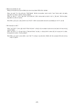
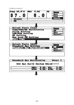
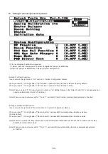
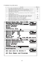
<Prior to setting each optional components>
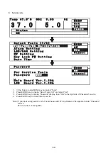
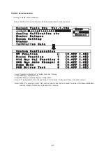
In “Select Tools Svc” display, select “System Configuration” and press MENU key.
Select “OK” and press ENTER key to display “System Configuration”.
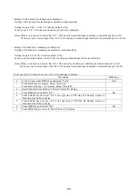
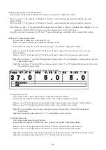
<Setting of UV lamp function>
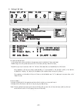
Input a value in the right side of “UV Function” in “System Configuration” display.
When you input “0” in the right side of “UV Function”, optional UV lamp function is inactive. (Factory default)
When you input “1” in the right side of “UV Function”, optional UV lamp function is active.
Note) When you select “0” (UV lamp function is inactive), “UV Setting” display in the “Select Tools (1/2)” is not appeared and
a device automatically returns to Top Screen.
Note) When you input a value except for “0” and “1”, optional UV lamp function is automatically selected to “inactive”.
<Setting of H2O2 decontamination>
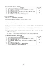
Input a value in the right side of “Decon Function” in “System Configuration” display.
When you input “0” in the right side of “Decon Function”, optional H2O2 decontamination function is inactive.
(Factory default)
When you input “1” in the right side of “Decon Function”, optional H2O2 decontamination function is active.
Note) When both optional UV lamp function and optional H2O2 decontamination function are unset, a device cannot step
to H2O2 decontamination mode.
Note) When you input a value except for “0” and “1”, optional H2O2 decontamination function is automatically selected
to “inactive”.
Содержание MCO-19M
Страница 7: ... 4 Dimensions Power cord ...
Страница 16: ...Wiring diagram 13 ...
Страница 17: ...Circuit diagram Main PCB 14 ...
Страница 18: ... LCD PCB 15 ...
Страница 110: ...MCO 19M UVH MCO 19M UV MCO 19M Multi Gas Incubator INSTRUCTION MANUAL 107 ...
Страница 112: ...CONTENTS SPECIFICATIONS P 74 PERFORMANCE P 75 SAFETY CHECK SHEET P 76 109 2 ...
Страница 183: ...Fig A Stacking plate B Stacking plate A Protective sticker Front panel Hook Front 180 73 ...
Страница 187: ...SANYO Electric Co Ltd Printed in Japan DC3186 150B ...

