ALARMS, SAFETY, AND SELF-DIAGNOSIS
The Incubator supports the following alarms, safety functions, and self-diagnostic functions.
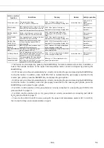
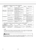
Table 1: Alarms and Safety Functions for Culture Operations
Alarm or safety
function
Conditions Display
Buzzer
Safety
operation
Upper limit
temperature
alarm
The chamber temperature exceeds the
upper limit alarm temperature set value.
OVERHEAT indicator lights.
Continuous tone
Heater OFF
Remote alarm
operates
Automatic set
temperature
alarm
The chamber temperature is out of the
automatic set temperature alarm setting
range (±1.0 to ±5.0
o
C).
Warning :High Temp
or
Warning :Low Temp
is displayed in the message display
field.
Intermittent tone
after set alarm delay
time (0 to 15 min)
has elapsed
Remote alarm
operates after delay
of 0 to 15 min.
Automatic set
CO
2
concentration
alarm
The chamber CO
2
concentration is out
of the automatic set CO
2
concentration
alarm setting range (±0.5% to ±5.0%).
Warning :High CO
2
Density
or
Warning :Low CO
2
Density
is displayed
in the message display field.
Intermittent tone
after set alarm delay
time (0 to 15 min)
has elapsed
Remote alarm
operates after delay
of 0 to 15 min.
Automatic set
O
2
concentration
alarm
The chamber O
2
concentration is out of
the automatic set CO
2
concentration
alarm setting range (±0.5% to ±5.0%).
Warning :High O
2
Density
or
Warning :Low O
2
Density
is displayed
in the message display field.
Intermittent tone
after set alarm delay
time (0 to 30 min)
has elapsed
Remote alarm
operates after delay
of 0 to 30 min.
Auto-return
There are no key operations for approx.
90 s in a setting mode.
Top screen is displayed.
-----
The setting mode is
canceled.
Key lock
The key lock is ON.
Key Lock
is displayed on the standby
operation setting screen.
-----
Setting changes are
prohibited.
Door alarm
The outer door is open.
Door
:
Open
is displayed in the
message display field.
Intermittent tone
after set alarm delay
time (1 to 30 min)
has elapsed
The CO
2
valve is
closed.
The N
2
/O
2
valve is
closed.
The heater turns
OFF after 1 min.
CO
2
gas
cylinder empty
The CO
2
concentration does not
increase when the CO
2
valve is
opened.
Err01: CO
2
Gas Empty
is displayed in
the message display field.
Intermittent tone
Remote alarm
operates.
N
2
(or O
2
) gas
cylinder empty
The O
2
concentration does not increase
when the N
2
/O
2
valve is opened.
Err02:
N
2
/O
2
Gas Empty
is displayed
in the message display field.
Intermittent tone
Remote alarm
operates.
CO
2
line
changeover
The CO
2
gas supply is switched
automatically to the reserve cylinder
(only when the MCO-21GC is installed).
Err01: CO
2
Gas Empty
is displayed in
the message display field.
The text flashes for the empty CO
2
gas
supply line.
〃
The CO
2
gas supply
is switched.
Remote alarm
operates.
N
2
(or O
2
) line
changeover
The N
2
/O
2
gas supply is switched
automatically to the reserve cylinder.
Err02:
N
2
/O
2
G
as Empty
is displayed
in the message display field.
The text flashes for the empty N
2
/O
2
gas supply line.
〃
The N
2
/O
2
gas
supply is switched.
Remote alarm
operates.
Connection
mistake of
CO
2
line and
N
2
(or O
2
) line
The CO
2
concentration keeps
increasing when the CO
2
valve is
closed.
Err03:
CO
2
G
as Connect
Abnormal is
displayed in the message display field.
〃
The CO
2
valve is
closed.
The N
2
/O
2
valve is
closed.
Selection
Mistake of
N
2
gas and
O
2
gas.
The O
2
concentration keeps keep
changing into the opposite direction
when the N
2
/O
2
valve is opened.
Err04:
N
2
/O
2
G
as Connect
Abnormal is
displayed in the message display field.
〃
The CO
2
valve is
closed.
The N
2
/O
2
valve is
closed.
Chamber
temperature
sensor error
The chamber temperature sensor is
disconnected.
Err05
:
Temp Sensor Open
is displayed in the message display
field.
〃
The heater turns
OFF.
Remote alarm
operates.
The chamber temperature sensor is
short-circuited.
Err06
:
Temp Sensor Short
is displayed in the message display
field.
〃
The heater turns
OFF.
Remote alarm
operates.
Sensor box
temperature
sensor error
The sensor box temperature sensor is
disconnected.
Err07: CO
2
S Box Temp Sensor Open
is displayed in the message display
field.
〃
CO
2
valve is closed.
Remote alarm
operates.
The sensor box temperature sensor is
short-circuited.
Err08
:
CO
2
S Box Temp Sensor Short
is
displayed in the message display field.
〃
CO
2
valve is closed.
Remote alarm
operates.
Ambient
temperature
sensor error
The ambient temperature sensor is
disconnected.
Err09: AT Sensor Open
is displayed in
the message display field.
〃
Remote alarm
operates.
The ambient temperature sensor is
short-circuited.
Err10: AT Sensor Short
is displayed in
the message display field.
〃
Remote alarm
operates.
CO
2
sensor
error
The Vref or Vgas output voltage for the
CO
2
sensor is abnormal.
Err11: CO
2
Sensor Vref Abnormal
or
Err12: CO
2
Sensor Vgas Abnormal
is
displayed in the message display field.
〃
CO
2
valve is closed.
Remote alarm
operates.
- 162 -
55
Содержание MCO-19M
Страница 7: ... 4 Dimensions Power cord ...
Страница 16: ...Wiring diagram 13 ...
Страница 17: ...Circuit diagram Main PCB 14 ...
Страница 18: ... LCD PCB 15 ...
Страница 110: ...MCO 19M UVH MCO 19M UV MCO 19M Multi Gas Incubator INSTRUCTION MANUAL 107 ...
Страница 112: ...CONTENTS SPECIFICATIONS P 74 PERFORMANCE P 75 SAFETY CHECK SHEET P 76 109 2 ...
Страница 183: ...Fig A Stacking plate B Stacking plate A Protective sticker Front panel Hook Front 180 73 ...
Страница 187: ...SANYO Electric Co Ltd Printed in Japan DC3186 150B ...

