77
6.13 Automatic Adjustment of Output Voltage (AVR)
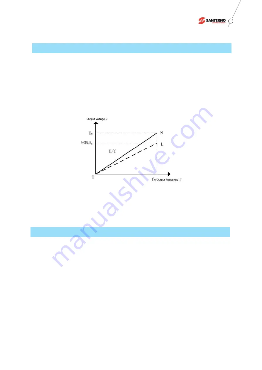
Figure 6-9 U/f line when the output voltage is reduced
In general, there is a certain fluctuation in the voltage of the power grid. When the power grid voltage fluctuates,
the DC bus voltage of the power cell will follow to fluctuate (the DC bus voltage is basically unchanged for fast
changes. In this case, even if there is no AVR function, the output can be stable), and the output voltage of VFD
will also change.
When the voltage fluctuation of the grid leads to the output voltage of the VFD becoming lower, it is known from
the diagram that the U/f line will change from the original ON to the OL shown by the dotted line, and the air gap
magnetic flux of the motor will decrease, and the actual load capacity of the motor will decrease.
In order to improve the situation,
SINUS MV
MV VFD detects the output voltage in real-time. When the grid voltage
changes within a certain range, the internal of the VFD can automatically adjust the output voltage of the VFD by
the control algorithm and the output voltage of the VFD keeps essentially unchanged, and the motor driving load
ability hold constant.
6.14 Power Cell Bypass and Neutral Point Drift
The cells in each phase of the
SINUS MV
MV VFD are connected in series. When one or several cells of the VFD
have a fault (including drive fault, overheat fault and fuse fault), bypassing the fault cell/cells will not affect the
current output capacity of the VFD, but its voltage output capacity will decline. Usually the output voltage of the
VFD is proportional to the output frequency. Therefore, when the maximum voltage of the output of the VFD is
limited, the maximum output frequency of the system will also decrease accordingly. Therefore, how to output the
maximum effective voltage after one or more cells of the VFD have been bypassed becomes critical.
We will take the 5 cell
SINUS MV
MV VFD as an example to show the high output ability even after the cell
bypassed.
Figure 6.10 is the output voltage structure of the 5 cell per phase MV VFD, each phase has 5 cells connected
in series, in this figure, all of the cells are normal and no fault, so the voltage angle among the phase A, B, C is
120°. Take phase A as an example, A1 means phase A the first stage cells, A2 means phase A the second stage,
and so on.


