


DMA CONTROLLER
S3C2416X RISC MICROPROCESSOR
8-12
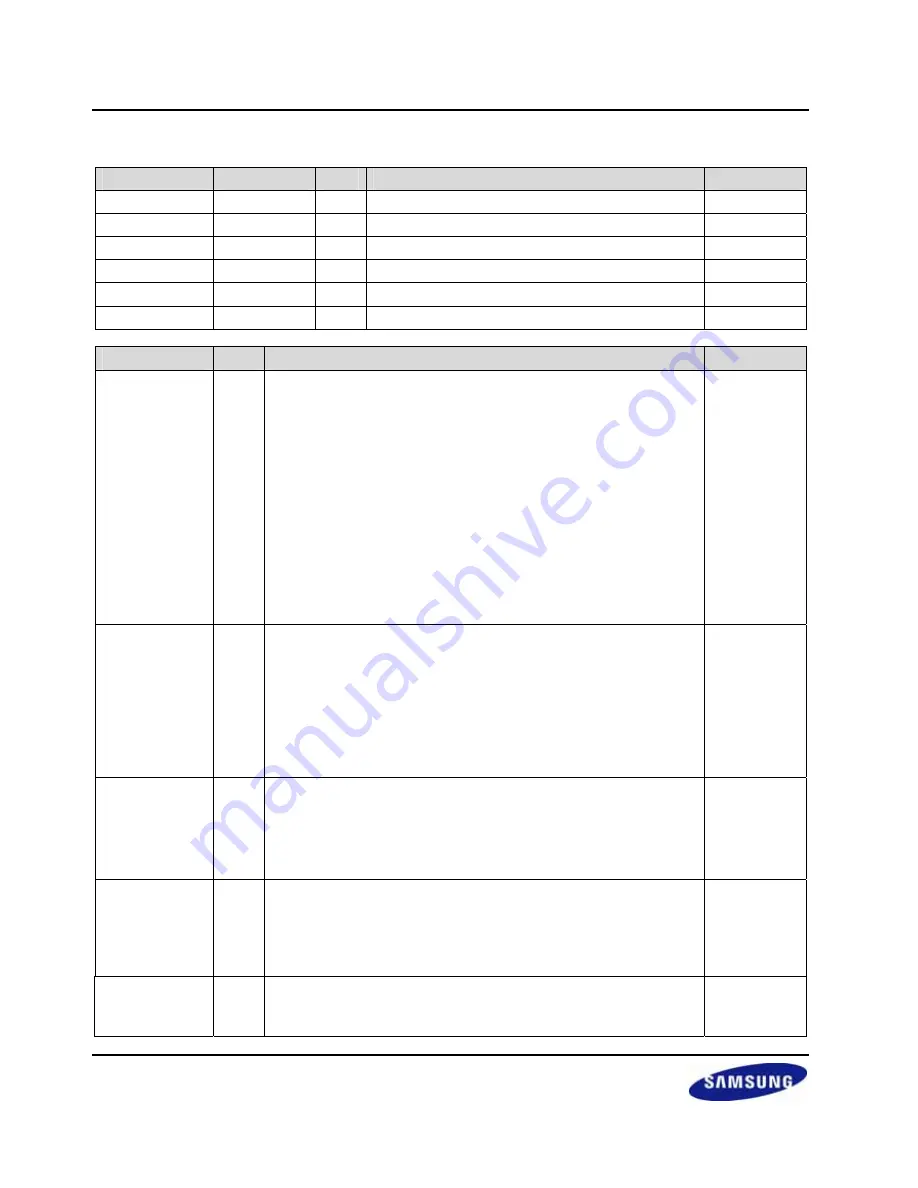
4.5 DMA CONTROL REGISTER (DCON)
Register
Address
R/W
Description
Reset Value
DCON0 0x4B000010
R/W
DMA0
Control Register
0x00000000
DCON1 0x4B000110
R/W
DMA1
Control Register
0x00000000
DCON2 0x4B000210
R/W
DMA2
Control Register
0x00000000
DCON3 0x4B000310
R/W
DMA3
Control Register
0x00000000
DCON4 0x4B000410
R/W
DMA4
Control Register
0x00000000
DCON5 0x4B000510
R/W
DMA5
Control Register
0x00000000
DCONn
Bit
Description
Initial State
DMD_HS
[31] Select one between demand mode and handshake mode.
0 = demand mode is selected
1 = handshake mode is selected.
In both modes, DMA controller starts its transfer and asserts DACK
for a given asserted DREQ. The difference between two modes is
whether it waits for the de-asserted DACK or not. In handshake
mode, DMA controller waits for the de-asserted DREQ before
starting a new transfer. If it sees the de-asserted DREQ, it de-
asserts DACK and waits for another asserted DREQ. In contrast, in
the demand mode, DMA controller does not wait until the DREQ is
de-asserted. It just de-asserts DACK and then starts another
transfer if DREQ is asserted. We recommend using handshake
mode for external DMA request sources to prevent unintended
starts of new transfers.
0
SYNC [30]
Select
DREQ/DACK synchronization.
0 = DREQ and DACK are synchronized to PCLK (APB clock).
1 = DREQ and DACK are synchronized to HCLK (AHB clock).
Therefore, devices attached to AHB system bus, this bit has to be
set to 1, while those attached to APB system, it should be set to 0.
For the devices attached to external system, user should select this
bit depending on whether the external system is synchronized with
AHB system or APB system.
0
INT
[29] Enable/Disable the interrupt setting for CURR_TC(terminal count)
0 = CURR_TC interrupt is disabled. User has to look the transfer
count in the status register. (i.e., polling)
1 = Interrupt request is generated when all the transfer is done (i.e.,
CURR_TC becomes 0).
0
TSZ
[28] Select the transfer size of an atomic transfer (i.e., transfer
performed at each time DMA owns the bus before releasing the
bus).
0 = A unit transfer is performed.
1 = A burst transfer of length four is performed.
0
SERVMODE
[27] Select the service mode between single service mode and whole
service mode.
0 = Single service mode is selected in which after each atomic
0
Содержание S3C2416
Страница 33: ...S3C2416X RISC MICROPROCESSOR PRODUCT OVERVIEW 1 5 3 BLOCK DIAGRAM Figure 1 1 S3C2416X Block Diagram ...
Страница 38: ...PRODUCT OVERVIEW S3C2416X RISC MICROPROCESSOR 1 10 153 AIN 1 U14 195 EINT 10 GPG2 K15 237 SDATA 14 C18 ...
Страница 122: ...BUS MATRIX EBI S3C2416X RISC MICROPROCESSOR 3 4 NOTES ...
Страница 204: ...DMA CONTROLLER S3C2416X RISC MICROPROCESSOR 8 18 NOTES ...
Страница 284: ...WATCHDOG TIMER S3C2416X RISC MICROPROCESSOR 11 6 NOTES ...
Страница 320: ...REAL TIME CLOCK S3C2416X RISC MICROPROCESSOR 13 16 NOTES ...
Страница 344: ...UART S3C2416X RISC MICROPROCESSOR 14 24 NOTES ...
Страница 380: ...USB2 0 DEVICE S3C2416X RISC MICROPROCESSOR 16 34 NOTES ...
Страница 432: ...2D S3C2416X RISC MICROPROCESSOR 18 38 NOTES ...
Страница 446: ...HS_SPI CONTROLLER S3C2416X RISC MICROPROCESSOR 19 14 NOTES ...
Страница 455: ...S3C2416X RISC MICROPROCESSOR HSMMC CONTROLLER 20 9 4 9 SD COMMAND ISSUE SEQUENCE Figure 20 9 Timeout Setting Sequence ...
Страница 604: ...S3C2416X RISC MICROPROCESSOR S3C2416X RISC MICROPROCESSOR 23 22 NOTES ...
Страница 638: ...PCM AUDIO INTERFACE S3C2416X RISC MICROPROCESSOR 25 18 NOTES ...
Страница 653: ...S3C2416X RISC MICROPROCESSOR ELECTRICAL DATA 26 15 Figure 26 14 SDRAM READ WRITE Timing Trp 2 Trcd 2 Tcl 2 DW 16 bit ...
Страница 670: ...ELECTRICAL DATA S3C2416X RISC MICROPROCESSOR 26 32 NOTES ...
Страница 672: ...MECHANICAL DATA S3C2416X RISC MICROPROCESSOR 30 2 Figure 27 2 330 FBGA 1414 Package Dimension 2 Bottom View ...


