background image

111

Tel: 886.2.2175 2930 Email: [email protected]

www.salukitec.com

xy

0Y

0X

0Y

0X

xy

s

S

Z

1

Z

1

Z

1

Z

1

2

S

Z

t

s

ts

Z

1

Y

t

Inverse:

xy

S

1

Adjoint

:

It means to conjugate on complex

xy

S

,in which,

0X

Z

and

0Y

Z

represent the characteristic

Impedance of port X and port Y respectively.
When the impedance conversion function in the fixture simulator is enabled, the characteristic impedance of corresponding port is
the set value in the impedance conversion. Otherwise, use the system impedance

0

Z

(default value is 50Ω).

6.9.

Setting Time Domain Transformation Measure

6.9.1.

By mouse or touch screen

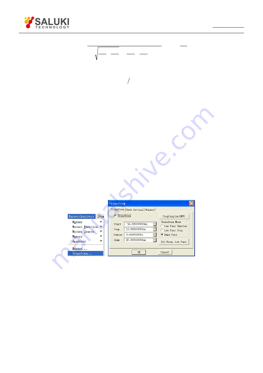
1) Click [Marker/Analysis], click [Transform...] in submenu to display Time Domain Transform dialog box.
2) Click to select [Transform] check box and Stimulus time domain transformation function.
3) Click [Start], [Stop] or [Center], [Span] box to set time domain Measure range.
4) Select transformation mode in Transformation Mode zone: [Low Pass Impulse], [Low Pass Step] or [Band Pass].

Fig.6-27 Setting Time Domain Transformation Measure

5) Set Window function: click [Window] Selection Button in Time Domain Transform dialog box and set window filter with

three methods below:

Drag sliding box with mouse till pulse width or sidelobe level meets the requirement.

Click [Gaesarian Window β Para] to adjust setting of value β, till pulse width or sidelobe level meets the requirement.

Click [Pulse Span] to set response pulse width directly.

Содержание S3601 Series

Страница 1: ...S3601 Series Vector Network Analyzer User Manual Saluki Technology Inc ...

Страница 2: ...20204 N type 75Ω calibration kit S3601A 07 Economical stable phase testing cable Saluki N J SMA J 197C 800 N type to 3 5mm connector dual male 80cm S3601A 08 Economical stable phase testing cable Saluki N J N K 197C 800 N type connector female male 80cm S3601A 09 Economical stable phase testing cable Saluki N J N J 197C 800 N type connector dual male 80cm S3601A 10 75Ω testing cable 24 0800 51M1 5...

Страница 3: ...ale to male 2 port S3601B 12 20403 Electronic calibration kit 10MHz 26 5GHz 3 5mm female to male 2 port S3601B 13 20405 Electronic calibration kit 10MHz 20GHz 3 5mm female 4 port S3601B 16 Aluminum carrying case S3601B 18 2813A 4 port test equipment Need option S3601B 29 S3601B 19 Cabinet Easy to build system S3601B 21 20201 N type calibration kit DC 9GHz S3601B 22 20202 3 5mm calibration kit DC 9...

Страница 4: ...stigate and affix legal liability of infringement Product Quality Certificate The product meets the indicator requirements of the manual at the time of delivery Calibration and measurement are completed by the measuring organization with qualifications specified by the state and relevant data are provided for reference Quality Environment Management Research development manufacturing and testing o...

Страница 5: ... 886 2 2175 2930 Email sales salukitec com www salukitec com 5 Contacts Service Tel 886 909 602 109 Website www salukitec com Email sales salukitec com Address No 367 Fuxing N Road Taipei 105 Taiwan R O C ...

Страница 6: ...Zone 19 3 1 8 Soft keys 21 3 1 9 USB Interface 21 3 1 10 Display Screen 22 3 1 11 On Standby Key and Indicator Light 22 3 1 12 Measure Ports 23 3 2 Rear Panel Tour 23 3 2 1 10MHz Reference Connector 24 3 2 2 GP IB Connector 24 3 2 3 VGA Output Connector 24 3 2 4 LAN Connector 25 3 2 5 USB Connector 25 3 2 6 External Trigger Input Connector 25 3 2 7 External Trigger Output Connector 26 3 2 8 Power ...

Страница 7: ...etting Frequency Range 41 4 4 Setting Signal Power Level 42 4 4 1 Setting Power Level 42 4 4 2 Turning Port Power Off 43 4 5 Sweep Setup 44 4 5 1 Sweep type 44 4 5 2 Setting of Sweep Type 44 4 5 3 Sweep Time 51 4 6 Selecting Triggering Mode 53 4 6 1 Simple Trigger Settings 53 4 6 2 Detailed Trigger Settings 53 4 7 Selecting Data Format and Scale 57 4 7 1 Data Format 57 4 7 2 Setting of Data Format...

Страница 8: ...n 74 5 1 5 Enhanced Response Calibration 75 5 1 6 1 Port Reflection 75 5 1 7 Quick SOLT 75 5 1 8 Full Dual port SOLT 76 5 1 9 Full Dual port TRL 76 5 2 Calibration Setup 77 5 2 1 Starting Calibration 77 5 2 2 Calibration User Configuration 80 6 Data Analysis 81 6 1 Marker 81 6 1 2 Moving the marker 83 6 1 3 Marker Search 84 6 1 4 Marker Function 86 6 1 5 Advanced Marker Option Setting 87 6 1 6 Mar...

Страница 9: ... De embedding 106 6 7 3 Matching circuit embedding 107 6 8 Parameter Transformation 110 6 8 1 Parameter transformation 110 6 8 2 Function type of parameter transformation 110 6 9 Setting Time Domain Transformation Measure 111 6 9 1 By mouse or touch screen 111 6 9 2 By front panel keys Time Domain Transform Dialog Box 112 7 Data Output 114 7 1 Saving and Calling back Files 114 7 1 1 Saving File 11...

Страница 10: ... 131 8 5 2 Reflection Measure in Band Pass Mode 132 8 5 3 Transmission Measure in Band Pass Mode 133 8 5 4 Fault Location by the Use of Low Pass Mode 134 8 5 5 Reflection Measure in Low Pass Mode 134 8 5 6 Transmission Measure in Low Pass Mode 135 8 6 Band Pass and Low Pass Time Domain Modes 135 8 6 1 Modes Comparison 135 8 6 2 Mode Selection 136 8 6 3 Frequency Span and Number of Points 136 8 6 4...

Страница 11: ...ort response isolation and enhanced response the calibration of full double ports and the electric calibration The color LCD display in multiple windows and channels and a number of interfaces such as USB interface LAN network port GP IB interface and VGA interface are also provided The S3601 Series Vector Network Analyzer can measure quickly and accurately the characteristics of the tested part D...

Страница 12: ...king container in shipping and avoid falling or violent collisions in moving which may cause damages to the device b Use AC DC adapter shipped with the device to supply power to the product Using other power adapters may case damages to internal hardware c Use 220V three wire regulated voltage AC power supply to prevent high power spike pulse interference from damaging internal hardware d Ensure t...

Страница 13: ...ternal of the device d Before using this device personnel need to be trained When using the device concentration is required Operation by unqualified people may cause personal injuries and property losses e Use of this device when power line is broken is prohibited Regular check on power line is necessary Proper measures should be taken to keep power line in good state and prevent stumble and elec...

Страница 14: ...yed as XXX and XXX is the names of menus and keys 3 1 Front Panel The front panel of S3601 Series vector network analyzer is shown in the following figure including a number of key functional zones display zones USB interfaces and Measure ports The section will describe the function and performance index of each part in details Fig 3 1 Front Panel of the Analyzer 1 Adjust Key Zone 2 Utility Key Zo...

Страница 15: ...n vector network is entered it is operatable by moving mouse arrow towards both left and right Default position of mouse arrow is bottom right corner of the screen and Move choice menu items in the menu upwards and downwards It plays the following roles in dialog box Change numeral value Select items in dropdown list Select the desired option in a group of option buttons When operation interface o...

Страница 16: ...ngs and printer for printing Micro Local When Analyzer is in external control state press this key to make the Analyzer re respond to the buttons on front panel When Analyzer is in normal working state press this key to access a set of user defined macros associated with executable files Analyzer can name and store 10 macros at most F 1 It is used to record shortcut keys in operating a certain Mea...

Страница 17: ...cale at which the Measure trace is displayed on the analyzer Display It is used to create a new window select or Stimulus the current window or make display settings Avg With the key Avg the noise can be reduced by use of the Measure averaging function The analyzer reduces the effect of random noise on the Measure result by executing complex exponential average of a number of sweeps for designated...

Страница 18: ... the next trace curve Channel Next It is used to Stimulus the next channel curve Trace The corresponding trace soft key menu will be displayed Press the corresponding soft keys to make creation deletion or selection of the Stimulus traces Channel Display the corresponding channel soft key menu and make channel management with corresponding soft keys 3 1 5 Stimulate Zone Determining the range sweep...

Страница 19: ...nalysis Zone Controlling all aspects of data analysis including marker and mathematical calculation Fig 3 7 Marker Analysis Keys Marker It is used to Stimulus the marker and set the stimulus value of the marker The marker can provide digital reading of the Measure result The analyzer can support at most 9 markers and the reference marker R Search It provides the marker search function Press this k...

Страница 20: ...he utility key on the front panel to quickly open the dialog box for utility setting For example press the key Menu and then press the key Search to open the dialog box for search setting The marker will backspace to delete the previous entry by pressing this key after the value is entered Numeric Key The numbers 0 9 are included It is used to enter the value in Measure setting and complete entry ...

Страница 21: ...tive value 3 1 8 Soft keys They work with the keys in other utility areas on the front panel and can easily carry out all instrument operations without a mouse An additional key can be used as a user key Soft key menu associated with a key can be called up by pressing this key on front panel Fig 3 9 Soft keys 3 1 9 USB Interface USB interface can be used to connect keyboard mouse or other USB devi...

Страница 22: ...izontal refresh rate 37 88 kHz Brightness 350NIT 3 1 11 On Standby Key and Indicator Light On Standby switch the analyzer between On and Standbys condition For the On condition the indicator light is green For the Standbys condition the indicator light is orange When the analyzer is On press On Standby the analyzer will quit the application program switch off the power and enter Standbys condition...

Страница 23: ...external power supply Fig 3 12 On Standby Key and Indicator Light 3 1 12 Measure Ports Fig 3 13 Measure Ports of the Analyzer Measure ports of Analyzer are two type N female ports which can be switched between RF source and receiver to measure the measured piece in two directions yellow lamp is used to indicate current source output port The input damage level RF power 26dBm DC voltage 30V The dam...

Страница 24: ...ale connector provides reference signals with the following properties Output frequency 10MHz 10ppm Signal type sine wave Output level 10dBm 4dB Output impedance 50Ω 3 2 2 GP IB Connector GP IB connector is a 24 pin D female connector for sending and receiving GP IB SCPI command complying with IEEE 488 standard Fig 3 16 GP IB Connector 3 2 3 VGA Output Connector This is a 15 pin D female connector...

Страница 25: ...nnector This is a 10 100 BaseT Ethernet connector with standard 8 pin structure which can automatically select one from the two data rates Fig 3 19 LAN Connector 3 2 5 USB Connector The plughole of the connector is Type A configuration embedding 4 contacts Contact 1 is on the left providing two interfaces complying with USB 2 0 specification and the property of every interface is as below Contact ...

Страница 26: ...er cord with ground wire provided along with instrument is recommended 3 2 8 2 Power switch During the normal working process of Analyzer the power switch shall be kept in ON position and please do not turn off the instrument by the power switch or unplug the power cord which may cause faults on software or hardware of Analyzer 3 3 Display Screen User Interface The Analyzer interface refers to the...

Страница 27: ...itch to the Menu Dialog mode b Press the Tab keys and keys to browse the menu press the Click key to make a selection c Browse and set the dialog box through the Tab key if the dialog box is open d Entry values if necessary e Press the OK in the ENTRY area to close the dialog box if the dialog box is opened 3 3 2 Mouse Interface The following operations can be done by using mouse a Click on the me...

Страница 28: ...nge its setting Single click the corresponding Trace state button to activate the Trace and the detailed setting method is shown in Changing Stimulus State of Trace Part of Selecting Measure Parameter in Section 2 of Chapter V and the setting for Trace includes Parameters Format Scale Calibration ON OFF Trace Math Marker Electrical Delay Phase Bias Smoothing Time Domain Transformation 3 4 2 Channe...

Страница 29: ...ompletely independent Through the Response menu window display can be set Creating a new window By mouse or touch screen Click Response and in the drop down list click Display select New Window in the Windows and the analyzer will create a window which is defaults for no traces Fig 3 25 Creating a New Window By front panel keys a Press Display key in the RESPONSE area b In the soft key menu displa...

Страница 30: ...he current active window click Response in the Response menu click Display and in the lower menu select Max in the Windows 3 Point the mouse to the window you want to view with the full screen and press the right button of the mouse Click Max in the right button menu By front panel keys 1 Press the Display key in the RESPONSE menu Press Windows corresponding soft key on the right side of the scree...

Страница 31: ...enabling multichannel Setting Analyzer display Configure 4 port Measure 4 1 Resetting Analyzer 4 1 1 Reset state When Preset key is pressed the Analyzer will be returned to a default state which is known as reset state and the reset state for S3601 Series Vector Network Analyzer is set as follows Measure parameter S11 Frequency setting Start frequency 100kHz Stop frequency 3GHz 8 5GHz CW Time 2GHz...

Страница 32: ...lay Formats Format Scale Reference Position Reference Value Log magnitude 10dB 5 0dB Phase 45o 5 0o Group Delay 10ns 5 10fs Linear Magnitude 100mU 5 500mU Standing Wave Ratio 1U 5 6U Real Part 2U 5 0U Imaginary Part 2U 5 0U Polar Coordinate 1U None 1U Smith Chart 1U None 1U Response setting Number of channel 1 Intermediate frequency bandwidth 30kHz Avg off Avg factor 1 Smoothing off Smoothing fact...

Страница 33: ...in full span Marker table blank Marker coupling off Displaying all Trace markers on Limit test setting Limit test off Limit line display off Failure sound warning off Limit table setting Type OFF Start activation 100kHz Stop activation 8 5GHz Start response 100dB Stop response 100dB Time domain transformation setting Time domain transformation off Transformation mode band pass Transformation start...

Страница 34: ... use the existing state single click load exist file as user reset state button select state file from the opened dialog box to enable it and the selected file is used as state file for user reset by Analyzer 5 Click Enable user reset state to mark check box 6 Single click OK button to close the dialog box Fig 4 1 Define User Reset State By front panel keys 1 Press Menu key in ENTRY area 2 Press T...

Страница 35: ...ure Parameter We can set the Analyzer to use the following parameters to measure electrical properties of a device S parameter fixed ratio Arbitrary ratio Measure of user defined ratio Measure of non ratio power absolute power Measure 4 2 1 S parameter 4 2 1 1 Creating new S parameter Measure Trace By mouse or touch screen 1 Single click Trace single click New Trace in New Trace menu and display t...

Страница 36: ... window at the elimination 4 2 2 Arbitrary ratio Measure The arbitrary ratio Measure allows to select input signals and reference signals for ratio Measure from receivers A B R1 and R2 4 2 2 1 Creating new arbitrary ratio Measure Trace By mouse or touch screen 1 Single click Trace Chan single click New Trace in Trace menu and display the dialog box of Create New Trace 2 Single click More Type butt...

Страница 37: ...nctions cannot be performed 4 2 3 1 Creating new non ratio power Measure Trace By mouse or touch screen 1 Single click Trace Chan single click New Trace in Trace menu and display the dialog box of Create New Trace 2 Single click More Type button to display the dialog box of New Trace 3 Select the source output port of Analyzer from Source box 4 Click Scale Type to eliminate check box if marked 5 S...

Страница 38: ...odified 4 2 4 1 Changing Stimulus state of Trace By mouse or touch screen Single click Trace Status Bar on the upper part of window and the corresponding Trace becomes the current Active Trace Fig 4 5 Changing Stimulus State of Trace By front panel keys Press Trace Prev or Trace Next in TRACE CHAN area Or the following operation methods can be employed Press Trace in TRACE CHAN area and press the ...

Страница 39: ...o Measure from Reference zone 8 Single click OK button to close the dialog box after the setting is completed Fig 4 7 Changing Current Active Trace to be Arbitrary Ratio Type By front panel keys 1 Press Meas in RESPONSE area and single click the soft key corresponding to Measure to display Measure dialog box 2 Press Tab in ADJUST area to switch to More Type button and press Click to display Next l...

Страница 40: ...ne 7 Single click OK to close the dialog box after the setting is completed By front panel keys 1 Press Meas in RESPONSE area and single click the soft key corresponding to Measure to display Measure dialog box 2 Press Tab in ADJUST area to switch to More Type button and press Click to display Next level Measure dialog box 3 Press Tab in ADJUST area to switch to Source box and press and or rotate ...

Страница 41: ... 2 Wave Band Division of S3601 Series Wave Band S3601 A Frequency Range S3601 B Frequency Range B0 100kHz 5MHz 100kHz 8MHz B1 5MHz 10MHz 8MHz 8500MHz B2 10MHz 748MHz B3 748MHz 1500MHz B4 1500MHz 3000MHz 4 3 1 Setting Frequency Range There are two methods of setting frequency range Designating start frequency and stop frequency Designating center frequency and frequency span 4 3 1 1 Setting start f...

Страница 42: ... set frequency span value in existing input bar 4 4 Setting Signal Power Level Power level refers to the power level for Analyzer measuring port output source signals and the technical index for power level of output signals at port of S3601 Series Vector Network Analyzer is as below Table 4 3 Source Signal Power Level Index Frequency Source Power Range dBm Resolution dB S3601A 100kHz 3GHz 45 10 0...

Страница 43: ...ck box and the power level settings for 2 ports of Analyzer are identical When Coupled Port Power check box is eliminated the Analyzer allows to set power level for every port respectively If the input power at Measure port of Analyzer is too large it may burn the receiver of Analyzer and the maximum input radio frequency power level at Measure port of Analyzer is 26dBm Port Power Level It is used...

Страница 44: ...ge is 25dB and the default power sweep range is 15dBm 10dBm During sweep the power is swept with scattered step value from start value to end value and the step size is decided by Sweep spot number and power range CW Time For this sweep type Analyzer is set to single sweep frequency The measuring data is sampled continuously and precisely in time interval decided by Sweep time and measuring points...

Страница 45: ... 3 Press Start in STIMULUS area and enter start frequency in Start Frequency box press Stop in STIMULUS area and enter stop frequency in Stop Frequency box 4 Press Sweep Setup in STIMULUS area press the soft key corresponding to Number of Points and enter Sweep spot number in Number of Points box 4 5 2 2 Setting of sweep type logarithm frequency By mouse or touch screen 1 Click Stimulus then click...

Страница 46: ... and enter start frequency in start frequency box press Stop in Stimulus area and enter stop frequency in stop frequency box 4 Press Sweep in STIMULUS area press the soft key corresponding to Number of Points and enter Sweep spot number in Number of Points box 4 5 2 3 Setting of power sweep type By mouse or touch screen 1 Click Stimulus then click Sweep Type from menu Sweep to show dialog box Swee...

Страница 47: ... center frequency value in CW Frequency box 4 Press Sweep in STIMULUS area press in soft key menu the soft key corresponding to Power press in submenu the soft key corresponding to Start Power and input start power in Start Power box press the soft key corresponding to Stop Power and enter stop power in Stop Power box 4 5 2 4 Setting of CW Time sweep type By mouse or touch screen 1 Click Stimulus ...

Страница 48: ... menu Press soft key corresponding to CW Time and enter center frequency value in CW Frequency 4 Press Sweep Setup in STIMULUS area press the soft key corresponding to Sweep Time and enter Sweep time in Sweep Time box press the soft key corresponding to Number of Points and enter Sweep spot number in Number of Points 4 5 2 5 Setup of segment sweep type By mouse or touch screen 1 Click Stimulus the...

Страница 49: ...ent sweep list By front panel keys 1 Press Sweep in STIMULUS area and press the soft key in soft key menu corresponding to Sweep Type 2 Press the soft key corresponding to Segment Sweep to select the sweep type 3 Press the soft key corresponding to Segment Table on OFF to show segment table for edit 4 5 2 6 Insertion and deletion of segment The segment table can be edited only when it s in display...

Страница 50: ... 1 Double click State for segment select ON or OFF to open or close segment 2 Double click Start for segment and enter start frequency of the segment 3 Double click Stop for segment and enter stop frequency of the segment 4 Double click Points for segment and enter Sweep spot number of the segment 5 Double click PWR for segment and enter power level of the segment when Independent Power Level opti...

Страница 51: ...equal to 300 milliseconds Analyzer will display a Sweep indicator to indicate a point to point Measure Sweep Sweep indicator is an upward small arrow pointing to the point on the Trace which just finished Measure 4 5 3 1 Setting of Sweep time By mouse or touch screen 1 Click Stimulus then click Sweep Time in menu Sweep to show Sweep Time dialog box 2 Enter Sweep time in Sweep Time box 3 Click OK t...

Страница 52: ...lect the check box 6 After setting press OK in ENTRY area to close the dialog box 4 5 3 3 Sweep Setup dialog box Channel box Select the channel adaptable to Sweep Setup Step Sweep check box When Step Sweep mode is selected the source will be tuned to a frequency measuring point waiting for measuring of this frequency point after a specified dwell time and then it will be tuned to the next frequenc...

Страница 53: ...y mouse or touch screen 1 Click Stimulus and point to Trigger in Stimulus menu to show the submenu of Trigger 2 Select the trigger mode needed in the submenu Fig 4 19 Simple Trigger Mode By front panel keys 1 Press Trigger in STIMULUS area to show corresponding soft key menu 2 Press the corresponding soft key to select the trigger mode needed 4 6 2 Detailed Trigger Settings 4 6 2 1 By mouse or tou...

Страница 54: ...y when the Analyzer is not Sweep The Analyzer may select 3 types of trigger source internal manual and external Once the trigger source is set the Analyzer will apply this trigger source to all channels Internal default The Analyzer will automatically control the generation of trigger signal The Analyzer will generate a trigger signal immediately after a Measure Manual Manual trigger signal may be...

Страница 55: ...ger Source is set to be manual status When Channel setting is selected spot sweep function will be available Channel Trigger State zone Trigger settings determine how many trigger signals will be received by one channel There are four channel trigger status Continuous The channel will receive unlimited trigger signals and continue to sweep Group The channel will receive the trigger signal with the...

Страница 56: ... zone High level When the Analyzer is ready for triggering it will trigger at the high level of the selected TTL input signal Low level When the Analyzer is ready for triggering it will trigger at the low level of the selected TTL input signal Positive edge When the Analyzer is ready for triggering it will trigger at the next rising edge of the received signal Negative edge When the Analyzer is re...

Страница 57: ...ar grid format This is most suitable for displaying frequency response information of the measured piece Rectilinear coordinate will display the following information By default X axis displays stimulus value in linear scale frequency power or time Y axis displays the corresponding response value at different stimulus values Fig 4 23 Rectilinear Coordinate Format The 7 data formats displayed in re...

Страница 58: ...ve value Y axis no unit Suitable typical Measure time domain Measure auxiliary input voltage signal Measure for maintenance purpose Imaginary format Display the imaginary part of measuring complex data only Y axis no unit Suitable typical Measure impedance Measure when matching network is designed 4 7 1 2 Polar coordinate format Polar coordinate format includes magnitude and phase information and ...

Страница 59: ...ith Chart represents pure resistance and the center point of horizontal axis represents system impedance the far left resistance is zero which represents short circuit the far right resistance of horizontal axis is infinite which represents enabled circuit On the chart the points on the circle intersecting with horizontal axis have the same resistance value On the chart the points on the circle or...

Страница 60: ...full scale of the outer circle The scale and format settings determine the display mode of measuring data on the screen In Logarithmic format the scale setting range is 0 001dB grid 500dB grid 4 7 3 1 By mouse or touch screen 1 Click Response point to Scale in Response menu to show submenu Click Scale to show Scale dialog box 2 Click the corresponding input zone or button to set suitable scale ref...

Страница 61: ... Click All Auto Scale button the Analyzer will set suitable scale for all Traces in the window to better show them in the vertical grid of the window Reference setting zone Position Reference position refers to the position of the reference line in rectangular chart In the chart the position of the line at the bottom is 0 the position of the line at the top is 10 and the default value at reference...

Страница 62: ...C Setting C will create three Traces in three windows and channel 1 setting S11 Smith Chart format displays in window 1 S22 Smith Chart format displays in window 2 and S21 log magnitude format displays in window 3 Setup D Setting D will create four Traces in two windows two channel settings and log magnitude format S11 and S21 display in window 1 channel 1 setting S12 and S22 display in window 2 c...

Страница 63: ...key toolbar Press corresponding soft key to Window select the window to be Stimulus and press the soft key corresponding to More to set window display The Display menu item in Response menu of Analyzer provides four window arrangements which can allocate the existing Traces to different windows according to certain arithmetic The said window arrangement modes include Overlay 1 For this type of arr...

Страница 64: ...ng to the moving Trace with mouse Press the left key of mouse and hold on Drag the mouse until the mouse pointer turns to motion indicator pull the mouse pointer to Trace status bar of the purpose window release the left key and the Trace moving is over 4 9 Setting Analyzer Display We can define OSD on screen display by means of Display menu in Response menu of the Analyzer Optional screen display...

Страница 65: ...nel keys 1 Press Display in RESPONSE area the corresponding soft key tool bar turns up and press soft key corresponding to More 2 Press soft key corresponding to Status bar on OFF in the displayed soft key tool bar to enable the status bar display 4 9 2 Tool Bar The Analyzer can simultaneously display 6 different tool bars at most and it is quite easy to set up Measure by the tool bar Active input...

Страница 66: ...indow when the leftmost button in the Measure tool bar is uplifted and create S parameter Trace in the new window when the button is pressed down Sweep control tool bar Buttons on the sweep control tool bar respectively set up the trigger way of the Stimulus channel to be Hold mode Single Sweep and then enter into Hold mode Continuous Sweep Stimulus toolbar The Stimulus toolbar is used to observe ...

Страница 67: ...the corresponding soft key tool bar and press soft key corresponding to More 2 Press the soft key corresponding to Toolbars to display the Toolbars submenu 3 Press the wanted toolbar soft key enable the toolbar display when it is On and close toolbar display when it is Off 4 9 3 Tables The Analyzer can display the marker table limit table and segment table and it can observe and modify their setti...

Страница 68: ...POINT 4 9 3 3 Segment table Figure 4 35 Segment Table The segment table is used to set up and modify the segment Sweep and these settings contain Segment condition ON OFF Start and stop stimulus values of the segment Sweep spot number of the segment Power level each segment can be set up individually Intermediate frequency bandwidth each segment can be set up individually Sweep time each segment c...

Страница 69: ...formation to set up and observe Measure and the information contains Trace status bar Frequency Activation Marker reading One marker for each Trace Big marker Limit test result Limit line Title 4 9 4 1 Trace status bar The Trace status bar is displayed above each window on the screen and displayed contents are as follows Measure parameter and format Scale Reference value Clicking the Trace status ...

Страница 70: ... format 4 9 4 3 One marker for each Trace When checking this item only 1 marker can be enabled on each Trace 4 9 4 4 Big marker When checking this item the typeface of marker reading becomes bigger 4 9 4 5 Limit test result The limit test result PASS or FAIL is displayed at the lower right corner of each window 4 9 4 6 Limit line The limit line targets at Active Trace display in the designated win...

Страница 71: ...removing the tick Figure 4 38 Triggering of Measure Display By front panel keys 1 Press Display key in RESPONSE area and press the soft key corresponding to Display Items on the soft key menu 2 Press the soft key corresponding to Marker Display on the soft key menu The three items of Mkr Readout ON off One per Trace on OFF and Larde Readout on OFF will turn up press the corresponding soft key to s...

Страница 72: ...Memory in the MKR ANALYSIS area to display the corresponding soft key menu it is feasible to display corresponding Trace when pressing and checking the soft key corresponding to Data Trace or Memory Trace hide the corresponding Trace when removing the tick 4 9 6 Title Bar The title bar contains the main Measure applications title bar and window title bar and it displays window titles and window co...

Страница 73: ...to Title Bar on OFF display the title bar when it is ON and hide the title bar when it is OFF 4 9 7 User Configuration Display 4 9 7 1 By mouse or touch screen Single click UTILITY single click Configure on the System menu and single click User Config on the appearing submenus to display the User Configure dialog box Figure 4 41 User Configuration Dialog Box Tick the option Display markers on all ...

Страница 74: ...onse Calibration precision low to medium Measure parameters S11 and S22 The required calibration standard short circuit device The corrected system errors Reflection Tracing Measure application Reflection Measure on any port 5 1 3 Through Response Calibration precision medium Measure parameters S12 and S21 The required calibration standard through standard The corrected system errors Transmission ...

Страница 75: ...uit device and load The corrected system errors Directivity Source matching Reflection Tracing Transmission Tracing Measure application Transmission Measure in any direction Reflection Measure on any port 5 1 6 1 Port Reflection Calibration precision high Measure parameters S11 and S22 The required calibration standards open circuit device short circuit device and load The corrected system errors ...

Страница 76: ...orrected system errors Directivity Source matching Reflection Tracing Crosstalk Transmission Tracing Load matching Measure application Measure of all S parameters Measure requiring 12 errors correction to improve the Measure precision 5 1 9 Full Dual port TRL Calibration precision very high Measure parameters all The required calibration standards through standard reflection standard and transmiss...

Страница 77: ...equency button in Calibration dialog box to display the Frequency Start Stop dialog box Click OK to close Frequency Start Stop dialog box after completing frequency setting Figure 5 2 Setting Calibration Frequency 3 Click Calibration Type in Calibration dialog box to display the Calibration Type dialog box and Click OK to close Calibration Type dialog box after completing calibration type selectio...

Страница 78: ...rom the default calibration kit of Analyzer click Select CalKit in the Measure Mechanical Standard dialog box to display the Select Calibration Kit dialog box and select the used calibration kit in the box Click OK to close the Select Calibration Kit dialog box Figure 5 5 Selecting Calibration Kit 6 If it is required to set calibration standard click Select Std in the Measure Mechanical Standard t...

Страница 79: ...dards Dialog Box 8 If the Prompt dialog box in the top right corner of Measure Mechanical Standard dialog box is ticked when the button corresponding to the calibration standard e g N Male OPEN is clicked in the Multiple Standards dialog box the Prompt for Connect Cal standard dialog box will be displayed Click OK button to start Measure after confirming the connected calibration standard is corre...

Страница 80: ...onse calibration Measure for example Press the soft key corresponding to Response and press the soft key corresponding to Thru Response in the sub soft key menu Press the soft key corresponding to FWD THRU After this menu item turns into FWD THRU a calibration Measure is completed by pressing DONE Response 4 Repeat steps b through c to complete the required calibration standard Measures 5 2 2 Cali...

Страница 81: ...r can be used to read measured data search measured values of specified types and change the settings of Analyzer Each Trace can use 9 normal markers and 1 reference marker 6 1 1 1 Create a marker By mouse or touch screen marker toolbar 1 Click Response point to Toolbars on Display menu click and check Markers on Toolbar submenu then the Analyzer displays Marker toolbar 2 Select the marker to be e...

Страница 82: ...Marker Dialog Box to Create the Marker 6 1 1 3 By mouse or touch screen marker menu 1 Click Marker Analysis point to Marker on Marker Analysis menu display Marker submenu 2 Click and select the marker to be enabled on submenu Fig 6 3 Using Marker Menu to Create Marker 6 1 1 4 By front panel keys 1 Press Marker at MKR ANALYSIS area display the marker to be enabled in appropriate soft key menu toolb...

Страница 83: ...rker Click UpDown on Stimu to move the marker Press or in ADJUST area to move the marker b Click Stimulate box in Marker dialog box and move the marker by following methods Directly input marker stimulus values Revolve the knob to move the marker Click UpDown on Stimulate box to move the marker Press or in ADJUST area to move the marker c Move the marker by following methods in the Marker box of M...

Страница 84: ...te to search measured value 4 Click OK to close the dialog box Figure 6 4 Marker Search 6 1 3 2 By front panel keys 1 Press Search in MKR ANALYSIS area 2 Press corresponding soft key to select search function in soft key search toolbar 6 1 3 3 Marker Search dialog box Marker Select the marker which makes search definition and implements search function Search It is used to define the search scope ...

Страница 85: ...plitude value When searching peak value definition of peak must be made at first Definition of peak is made through threshold and shift boxes Threshold defines the minimum peak point The peak point of effective peak must be above threshold and valleys at both sides can be lower than threshold Bias defines the minimum vertical distance between peak point and valley point the vertical distance betwe...

Страница 86: ...s 3dB click Execute to make bandwidth Measure at this level Use marker 1 4 during Measure marker 1 searches the maximum peak value marker 2 searches the point at the left side of peak value dropping to the specified level marker 3 searches the point at the right side of peak value dropping to the specified level and marker 4 searches the center point of bandwidth and the following data will be sho...

Страница 87: ...g functions in the arisen marker function soft key toolbar Marker function dialog box Marker Start When clicking start value of Sweep Setup is equal to the value for Stimulus marker Marker Stop When clicking stop value of Sweep Setup is equal to the value for Stimulus marker Marker Center When clicking center value of Sweep Setup is equal to the value for Stimulus marker Marker Ref Level When clic...

Страница 88: ...nding marker display will be close if it is cleared Discrete Marker When it is selected marker only displays data at actual measuring point and it also displays interpolative data point between measuring points when it is cleared Format Select the format of marker to display measured data the format of marker data can be different from that of screen Trace data but they are same under the default ...

Страница 89: ...Y axis can remain unchanged This type of marker is mainly used to observe change of Trace marker for example the fixed type marker can be used to compare variance of insertion loss before and after tuning wave filter 6 1 6 Marker Table Marker Table can be enabled to display all marker data of Active Traces and marker data will be displayed in specified format of each marker 6 1 6 1 Settings of sho...

Страница 90: ... and close Marker Table display 6 2 Trace Math and Statistics Analyzer can carry out 4 types of mathematical operation to current Active Trace and storage Trace in addition it also provides 3 kinds of Trace statistical functions 6 2 1 Trace Math Before Execution of any type of Trace math a Trace must be saved in memory and Trace math is vector operation made on complex data before formatted displa...

Страница 91: ...d data will be saved in memory Data Math It is used to select Trace math type and the Analyzer supports the following Trace math Data it will not make any type of mathematical operation Data Memory it will implement addition computation for measured data and stored data Data Memory it implements subtraction operation for measured data and stored data and this function can be used for simple error ...

Страница 92: ...d ripple wave without searching maximum value and minimum value Statistic of Trace is calculated according to data display format Rectangular Coordinates Format statistic is calculated according to displayed scalar data Polar Coordinates and Smith Chart Format statistic is calculated according to display value of data in log magnitude format 6 2 2 1 Settings of Trace statistics By mouse or touch s...

Страница 93: ... will be displayed on screen in the form of limit line There are the following advantages for using limit line It provides the debugging personnel with an intuitive indication It provides index properties of a device meeting required standard It provides intuitive comparison between measured data of device and index requirements Limit test function can compare measured data with defined limits and...

Страница 94: ...type and press Click for confirmation of choice 3 Press Tab to shift to Begin Stimulus and press Click to Stimulus start activation input box and set up start stimulus value 4 Press Tab to shift to End Stimulus box and press Click to Stimulus stop activation input box and set up start stimulus value 5 Press Tab to shift to Begin Response box and press Click to Stimulus start response input box and...

Страница 95: ...ay or hide When the limit line is hidden corresponding limit test is still effective For limit test which can not be made for stored Traces it can be chosen to send out alarming and display FAIL information to instruct limit test When enabling limit test function failed part of traces for limit test will be displayed as red and passed parts of traces will remain unchanged You can change the color ...

Страница 96: ...on Fail When it is selected if Trace data point test is failed buzzer will send out warning tone FAIL Mark ON off When it is selected if Trace data point test is failed the mark of fail will be displayed on the screen Dot Use symbol v Measure type as MAX and Measure type as MIN to indicate corresponding discrete limit value of measured data point during selecting Line Use line to connect all discr...

Страница 97: ...nd set bandwidth test The bandwidth threshold N dB point maximum bandwidth and minimum bandwidth must be set before making bandwidth test and multiple traces can be set 6 4 1 1 By mouse or touch screen 1 Click Marker Analysis and click Limit Test on Analysis menu to display Limit Test 2 Click Bandwidth Test button in the dialog box to display bandwidth test dialog box Figure 6 15 Bandwidth Test Di...

Страница 98: ...ax BW and set maximum bandwidth in the input box 6 4 2 Display bandwidth test result The result of bandwidth test is displayed on the upper left side of the trace if the test is passed the word PASS will turn up on the screen The red T shaped bandwidth mark distribute on the two sides of bandwidth Figure6 16 Bandwidth Test Result Display 6 4 3 Close bandwidth test 6 4 3 1 By mouse or touch screen ...

Страница 99: ...ewly increased the filter test function which is used for the automatic test of filter The tested parameters of filter is automatically displayed on the screen this function simplifies the setup of filter test process and improves the test speed of filter 6 5 1 Open and close bandwidth searching Bandwidth searching can only be set through soft key menu 1 Press Search in MKR ANALYSIS area press cor...

Страница 100: ...int Low The lower frequency of the two points which are lower than the signal peak value on specific bandwidth level High The higher frequency of the two points which are lower than the signal peak value on specific bandwidth level 6 5 3 Filter test The analyzer is installed with a shortcut function for the test of filter All the tested parameters will be displayed on the screen and it is very con...

Страница 101: ...rresponding soft key of Freq Offset and set the value of frequeny difference percentage in the input box 10 Press corresponding soft key of Filter Test ON off to close filter test function 6 5 3 2 Display bandwidth searching result The eight parameters of filter test will be displayed on the upper left side of the trace Enabling the filter test the bandwith searching function will be activated aut...

Страница 102: ...8 The analyzer will add a new row to the limit table after opening the last row 9 Repeat step 4 7 to completer the editing and adding of all limit segments 6 6 1 2 By front panel keys 1 Press Analysis in MKR ANALYSIS area press corresponding soft key of Ripple Test on the soft key menu that turns up press Edit Ripple Limit and press Ripple Table on OFF on the sub menu to open the ripple limit tabl...

Страница 103: ...s set to red and you can change the color through the color setup of the right key menu of the mouse and the color of the passed part of the limit test remains unchanged 6 6 2 1 By mouse or touch screen 1 Click Marker Analysis click Limit Test in the Analysis menu to display the limit test box 2 Set the limit test in the dialog box 6 6 2 2 Click OK to close the box By front panel keys 1 Press Anal...

Страница 104: ... shifted to disabled state after the table is closed Export Click it storage dialog box will appear Users could select storage route and save the file with csv format Import Click it storage dialog box will appear Select the storage route of the file to be opened It can open the file of csv format Val Type Click the drop down box to select the ripple value type none absolute margin The default set...

Страница 105: ...ence impedance 6 7 1 1 By mouse or touch screen 1 Click Marker Analysis menu click Fixture Simulator on the menu of Analysis and click Fixture Simulator on OFF on the sub menu to open fixture simulator function 2 Click Marker Analysis menu click Fixture Simulator on the menu of Analysis and click Z Conversion on the sub menu to open impedance conversion dialog box 3 Click On Off Z to enable impeda...

Страница 106: ...orresponding value in the input box that turns up 6 7 2 Network De embedding Network De embedding function can eliminate any network characteristics defined by Touchstone data file snp between test plane and DUT plane to extend corresponding calibration plane 6 7 2 1 By mouse or touch screen 1 Click Marker Analysis menu click Fixture Simulator in the menu of Analysis and click Fixture Simulator on...

Страница 107: ...k de embedding function 4 Press the soft key of Select Port 1 2 to shift to corresponding port 5 Press the soft key of Select Type User None to shift to corresponding type User corresponds to the enabling of corresponding port None corresponds to the disabling of the corresponding port 6 Press the soft key of User File select the S2P file to be used in the dialog box that turns up and the file nam...

Страница 108: ...ponding to port1 and port2 the circuit type will be displayed at the lower part Enter the value of capacitance conductance inductance and resistance in corresponding editing box when the circuit type is USER the Self Define will be in enabled state click Self Define select the S2P file to be used in the dialog box that turns up and the file name will be displayed in the box aside ...

Страница 109: ...s corresponding soft key of Port Matching and press corresponding soft key of Port Matching on OFF in the sub menu that turns up to enable the matching circuit embedding function 4 Press corresponding soft key of Select Port 1 2 to shift to corresponding port 5 Press corresponding soft key of Select Circuit choose proper circuit type on the sub menu that turns up When the circuit type is User you ...

Страница 110: ...n the drop down menu Figure 6 26 Parameter Transformation Dialog Box 6 8 1 2 By front panel keys 1 Press Analysis in MKR ANALYSIS area and press Conversion in the soft key menu that turns up 2 Press Conversion on OFF to trigger the opening and closing of parameter transformation function 3 Press Function and select corresponding transformation type in the sub menu of soft key that turns up 6 8 2 F...

Страница 111: ...1 Click Marker Analysis click Transform in submenu to display Time Domain Transform dialog box 2 Click to select Transform check box and Stimulus time domain transformation function 3 Click Start Stop or Center Span box to set time domain Measure range 4 Select transformation mode in Transformation Mode zone Low Pass Impulse Low Pass Step or Band Pass Fig 6 27 Setting Time Domain Transformation Me...

Страница 112: ...sform dialog box and click to clear Transform check box 8 Click OK to close Time Domain Transform dialog box after setting 6 9 2 By front panel keys Time Domain Transform Dialog Box 1 Press Analysis in MKR ANALYSIS area press soft key corresponding to Transform relative soft key menu appears press corresponding soft key of Transform to display Time Domain Transform dialog box 2 Press Tab in ADJUST...

Страница 113: ... check box and Stimulus filtering function of time domain gate then set the function of time domain gate Press Tab to switch to Start Stop or Center Span to set gate border Press Tab to switch to Gate Type box press or rotate knob to select gate type band pass band stop Press Tab to switch to Gate Shape box press or rotate knob to select gate form minimum standard wide maximum 7 If it is necessary...

Страница 114: ...multiple formats 7 1 1 Saving File 7 1 1 1 By mouse or touch screen Click File click Save or Save As in file menu Figure 7 1 Saving File When clicking Save Analyzer will save instrument status and calibration data in default file of a specified directory and if default file already exists Analyzer will display a dialog box for confirming whether it is covered When click Save As Analyzer will open ...

Страница 115: ...on Analyzer will open Designated Data Storage Format dialog box and it will save Trace data as per user requirements prn file only to save current Stimulus Trace data bmp file to save screen display information of Analyzer in BMP format jpg file to save screen display information of Analyzer in jpeg format 7 1 2 Calling back file It can save Analyzer status and calibration data if necessary it wil...

Страница 116: ...n call back soft key toolbar press corresponding soft key of Recall to open dialog box and select call back file or change path and call files in other directories 7 1 3 Data File Data files save Measure results in ASCII format these files can be edited by using test editing software and spreadsheet software but can not be called back by Analyzer itself Analyzer can save three types data files 7 1...

Страница 117: ...n regulating keypad or rotate knob to select save file type as data file dat and press key of Enter keypad to complete selection 4 Set up file save directory via Save In and File List box 5 Press Tab to shift to File Name and set up the saved file name 6 Press in Enter keypad to display Data Save Setting dialogue 7 Set up content and format of saved file in the dialog box click Tab to shift to For...

Страница 118: ...four S parameters in s2p file If full double port correction is closed Analyzer will save as much as possible Measure data in s2p file For instance if full double port correction is closed current Stimulus Trace is S11 and S21Measure still exists in channel Measure results of S11 and S21 will be saved in s2p file because there is no effective Measure data of S11 and S21 corresponding data in s2p f...

Страница 119: ...ve As on File menu to display Save As dialog box 2 Set up file storage type as List File prn in Save as Type box 3 Set up file save directory via Save In box and File List box 4 Set up file name in File Name box 5 Click Save button to save file and close the dialog box By front panel keys 1 Press Save in UTILITY area 2 Press corresponding soft key of Save As to display Save As dialog box 3 Press T...

Страница 120: ...can be effective only when the check box is selected Print Active Window If selecting it only the content of current Stimulus window is printed Print All Windows If selecting it content information of all windows will be printed One Window per Page If it is selected one window is only printed per page if it is cleared all windows content will be continuously printed without forced page break Other...

Страница 121: ...log box 2 Click OK to begin print after print setup is completed in dialog box Figure 7 5 Print Measure Information 7 2 2 2 By front panel keys 1 Press Print in UTILITY area and press corresponding soft key of Print to display Print Setup dialog box 2 Press in ENTRY area to begin print after settings are completed 7 2 3 Printing to File Analyzer supports outputting the printed content to bmp file ...

Страница 122: ...122 Tel 886 2 2175 2930 Email sales salukitec com www salukitec com 2 Set up file save directory and file name in the dialog box 3 Press in ENTRY area to save file ...

Страница 123: ...ransmission line mismatch or impedance change Fig 8 1 Frequency Domain and Time Domain Measures Frequency domain response of S11 measured at input port indicates the combined reflection response caused by interaction of mismatched cable waves however definite physical location of the cable mismatch is hard to be determined Time domain response indicates location and size of each mismatch and we ca...

Страница 124: ...me domain data of the measured piece and how to set up the instrument to obtain highest resolution and maximum Measure range 8 2 1 Response Resolution Time domain response resolution of the Analyzer refer to the capability of Analyzer to distinguish two adjacent responses For response of identical amplitudes it equals to the pulse width of impulse response defined by 50 6dB amplitude point or the ...

Страница 125: ...tically according to current setting c Time domain transformation mode In low pass and band pass transformation modes resolutions of Measure responses are different For the same frequency span and Sweep spot number low pass mode has higher resolution and pulse width can reduce by half compared with band pass mode figure below provides the resolution comparison in two modes Fig 8 4 Effect of Transf...

Страница 126: ...sure range can be defined as the maximum time span set and no repeated response will occur within this time span when performing Measure Measure range has an inverse relationship with response resolution one increase the other will be reduced Time domain waveform is the periodic signal repeating with time thus repeated response will occur Repeated response false response is not true response of th...

Страница 127: ...n change exists at initial and terminal frequencies which will result in overshoot and ringing in step response of time domain Using window filtering function can reduce effect caused by sudden change in frequency domain besides Analyzer also has following deficiencies when performing time domain Measure Pulse width of impulse response or rise time of step response this is caused by limitation pro...

Страница 128: ...and dynamic range of Measure In low pass step transformation mode it can mitigate overshoot and ringing 8 3 2 Setting Window Value Correctly When performing time domain Measure proper window value must be selected according to response type of the measured piece Response of the measured piece with identical amplitude small window is selected to obtain narrow pulse width to improve resolution of ti...

Страница 129: ...Measure steps with time domain gate function are as follows a Measure the measured piece in frequency domain b witch on time domain transformation function and the Analyzer will calculate time domain response of the measured piece c Select gate type Band pass set the gate at the center requiring response reservation switch on gate function and response outside the gate is removed from the displaye...

Страница 130: ... 3 1 Passband ripples of the gate The gate is a pass band or band stop wave filter on time domain and each form of wave filter has different filter property Figure below indicates band pass ripples of four filters in different forms and the scale in the figure is 0 5dB grid It can be seen from the figure that the minimum gate has the largest band pass ripples Fig 8 11 Band Pass Ripples of Differen...

Страница 131: ...e If the gate span set is smaller than this minimum value the Analyzer will produce effects below The gate form is distorted without pass band Indication of start and end time is incorrect Sidelobe level would be increased 8 5 Time Domain Measure Data This section will provide examples of various Measure types to facilitate understanding of time domain response of the measured piece 8 5 1 Screenin...

Страница 132: ...reening caused by energy absorption happens when measuring loss circuit In Measure below an open circuit device is terminated to a cable and the Measure result displays the screening caused by energy absorption Fig 8 14 Effect of Screening Caused by Energy Absorption toward Measure Result Marker 1 displays that return loss of open circuit device is 2 5dB observed in the format of logarithm amplitu...

Страница 133: ...ce Vertical axis data In the format of logarithm amplitude it represents transmission loss or transmission gain In the format of linear amplitude it represents transmission coefficient An example of surface filter SAW transmission Measure in band pass mode is provided below Fig 8 16 Transmission Measure in Band Pass Mode Three transmissions in surface acoustic wave SAW filter can be found from Mea...

Страница 134: ...re can be performed by the use of low pass step or low pass impulse mode however it is easier to distinguish discontinuous types by the use of low pass step mode which is similar to Measure with conventional time domain reflectometer TDR Fig 8 17 Low Pass Time Domain Response Waveform of Discontinuous Circuit 8 5 5 Reflection Measure in Low Pass Mode Horizontal axis data It represents the time use...

Страница 135: ...to impulse mode only An example of low pass step response of amplifier is provided below Fig 8 20 Low Pass Step Measure Results of Amplifier Average group delay within Measure frequency range is the differential value between step and amplifier response Step rise time is directly related to highest frequency of frequency domain sweep the higher the frequency the shorter the rise time is Ringing of...

Страница 136: ...frequency response falls rapidly at low end select low pass mode also 8 6 3 Frequency Span and Number of Points 8 6 3 1 Band pass mode Any start and stop frequency can be selected within operating frequency range of the Analyzer The Analyzer utilizes all Measure data within start and stop frequency range It provides impulse response only 8 6 3 2 Low pass mode It is required to obtain direct curren...

Страница 137: ...in the whole Measure frequency range For transmission Measure this format represents transmission loss or gain dB and the display value represents average loss or gain of the transmission path within the whole Measure frequency range This format is very useful to observe the response of dynamic range Standing wave ratio For reflection Measure this format represents the average value of standing wa...

Страница 138: ...ra to adjust setting of value β till pulse width or sidelobe level meets the requirement Click Pulse Span to set response pulse width directly Fig 8 22 Time Domain Transformation Measure Setting Window f Set filtering function of time domain gate click Gate Setting option button in Time Domain Transform dialog box and click to select Gating check box to enable filtering function of time domain gat...

Страница 139: ...ing change toward Measure can be observed clearly See Trigger Toolbar Display in Section 9 Setting Analyzer Display in Chapter V for setting method of Time Domain toolbar 8 7 2 By front panel keys Time Domain Transform Dialog Box a Press Analysis in MKR ANALYSIS area press soft key corresponding to Transform relative soft key menu appears press corresponding soft key of Transform to display Time D...

Страница 140: ... rotate knob to select gate type band pass band stop Press Tab to switch to Gate Shape box press or rotate knob to select gate form minimum standard wide maximum g If it is necessary to observe frequency domain response of the measured piece when the gate function is still effective press Tab to switch to Gate Setting option button press or rotate knob to switch to Transform option button press Ta...

Отзывы: