54
SLC CUBE 3+
11:19:35 11/09/2013
screen 0.0
(
)
(
)
(
)
(
)
(
)
(
)
(
)
(
)
(
)
(
)
(
)
(
)
(
)
(
)
CONTROL
&
STATUS
OF THE UNIT
MEASURES
PARAMETERS
ALARMS
DATA LOGGER
CONFIGURATION
Password: *****
RATED VALUES
screen 1.0
screen 2.0
screen 3.0
screen 4.0
screen 5.0
(*1)
screen 6.0
screen 7.0
(
)
(
)
(
)
(
)
(
)
(
)
(
)
(
)
(
)
(
)
(
)
(
)
(
)
(
)
(
)
(
)
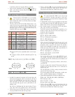
Firmware versions, serial number,
configurations, ...
Unit Start-up, battery test com-
mand, …
Measurements: voltages, currents,
power, temperatures, …
Basic parameters programmation:
date, time, language, communica-
tions, …
Active alarms.
Last 100 alarms
&
events occurred
can be displayed in this submenu,
and also the status of the unit at that
moment.
Configuration of the unit, measures
calibration, internal parameters ad-
justment, …
For Technichal Service only
(password required).
At user level, inspection of some
rated values like input
&
bypass
voltage, input & bypass margins, DC
voltage, output current, charging bat-
tery current and battery probe..
Fig. 43.
Classification of the menus and submenus displayed in
the LCD panel.
7.3.
SCREEN DESCRIPTION.
7.3.1. Main level (screen menu 0.0). See Fig 44.
•
Screen 0.0
: Main presentation screen, with time and date indication.
SLC CUBE 3+
11:19:35 11/09/2013
UPS:
CFG:
DSP Ver.: ver. 3.2 a
Uc Ver.: ver. 2.4 b
UPS Serial Number
09 A-321899
screen 0.0
screen 0.1
screen 0.2
screen 0.3
(
)
(
)
(
)
(
)
(
)
(
)
When pressing key
(ESC)
from any screen of any submenu, it is
gone back to main screen
(Screen 0.0)
.
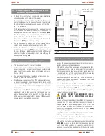
Fig. 44.
Screen 0.0 «Start» and its submenus.
•
Screen 0.0
: In parallel equipments, the first row of the screen
changes between “SLC CUBE3+” and “Paral.-- Out.SW=---”,
and where:
Paral. ---, corresponds to the address of each UPS with
three characters.
Out.SW ---, corresponds to the position of the output
switch of the UPS and/or switchgear panel board, with two
status ON and OFF (the auxiliary contact of the output switch
in the output panel board has to be connected according to
the instructions of section 5.2.9.2.).
•
Screen 0.1
: UPS Status (“UPS:”, 1
st
row) and configuration (‘‘CFG:”,
2
nd
row). In the first row, there are two fields, first one shows the
general state of the converters, and second one shows the origin of
the voltage at the output. These two fields are separated by a “ , “:
Possible states of the converters:
–
«Shutdown» Rectifier and Inverter stopped or blocked.
–
«Start up» UPS converters (rectifier and inverter) are
started up, but not ready yet.
–
«Normal» UPS is running in normal mode: mains present,
rectifier running, output on inverter, loads are protected.
–
«Discharge» Mains failure. UPS running on back-up
mode (rectifier shutdown, inverter running).
Origin of the output:
–
«OFF» No voltage supplied at the output (either EPO
pressed, or severe problem in the equipment).
–
«Invert» Inverter voltage is supplied at the output. Loads
are protected.
–
«Bypass» Bypass voltage is supplied at the output.
Either the equipment is manually shutdown, or over-
loaded, or other possible problem in the inverter.
In the second row, there is the hierarchy of the UPS as regards
to the rest of the system, which is dynamic depending on the
status of the rest of the equipments. For «Single» equipment,
the LCD will display the message «CFG: Single»
Equipment hierarchy (parallel systems):
–
«Paral. Mst. Byp» bypass Master of the parallel system.
By default, the first UPS starting up the inverter ac-
cording to the established procedure.
–
«Paral. Slv. By.Rsv» reserved bypass Slave. Initially cor-
responds to the equipment with the highest address ex-
cepting the one from «bypass Master». In case of failure
of the Master, it will take its functions.
–
–
«Paral. Slv. Byp» bypass Slave of the parallel system
(systems with more than two equipments only). It will
become as «reserved bypass Slave», when it practise
as «bypass Master». In systems with more than three
USER MANUAL


