47
SALICRU
• Continue with the described procedure in the next section,
considering that the stated actions in the first three steps are
already done.
6.2.3.2. Normal start up procedure.
• Supply input voltage to the switchgear panel board.
• Turn «On» the input switch or switches of the panel board, de-
pending if it is a single equipment or parallel system.
• Turn the UPS or each UPS input switch
(Q1a)
to «On» position.
The LCD of the Control Panel
(PC)
of each equipment will be
turned on automatically.
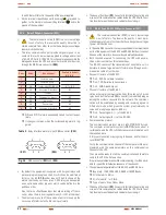
For single equipments the LCD panel will display the left mes-
sage of the screen 0.0 and for parallel systems both messages
will be displayed 0.0 :
SLC CUBE 3+
11:19:35 11/09/2013
screen 0.0
Paral. 002 Out. SW=OFF
11:19:35 11/09/2013
screen 0.0
Ì
É
Where in parallel systems, the right screen 0.0 corresponds to:
Paral. ---, address of each UPS with three characters, in the
example is 002.
Out.SW ---, the position of the output switch of the UPS
and/or switchgear panel board, with two status ON and OFF
(the auxiliary contact of the output switch in the output panel
board has to be connected according to the instructions of
section 5.2.9.2.).
• If the following alarm message appears on the LCD Control
Panel ...
MAINS PHASE ROT.
UPS START INH.
screen 4.*
... also an audible alarm will beep in each equipment with the
message in the screen and the affected UPS/s not be able to be
started up, due to the wrong input phase rotation.
If it happens in only one UPS of the parallel system, turn
«Off» the input switch
(Q1a)
of the corresponding equip-
ment and the one in the switchgear panel board. Swap two
phases of the input terminals of the UPS leaving the connec-
tions in the same order as the rest of the equipments and
repeat the start up procedure described up to now.
If it happens in all equipments of the parallel system, turn
«Off» the input switch
(Q1a)
of each UPS and input switches
of the switchgear panel board, swap two phases in the input
terminals of the switchgear panel and repeat the start up pro-
cedure described up to now.
• In equipments or systems with separate static bypass line
SLC
CUBE3+ B
:
Turn the bypass switches from panel board «On».
Turn the bypass switches
(Q4a)
of each UPS to «On».
• If the following alarm message appears on the LCD Control
Panel ...
BYPASS PHASE ROT.
UPS START INH.
screen 4.*
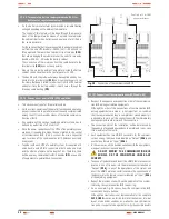
To begin the time and date setting press
(ENT)
. Each character
that has a value, it is modified one by one, to change the first
character of the field use the keys
(
)
and
(
)
and validate
with
(ENT)
. To jump to the next character use the keys
(
)
and
(
)
. To finish press
(ESC)
, the values will be validated and the
following screen is displayed.
UNIT NOMINAL VOLTAGE
3 X AAA V
... where AAA corresponds to the nominal phase to phase
value, of the operating voltage of the equipment.
• By means of the keys
(
)
and
(
)
, move it till the nominal
value of the power supply voltage and validate it with
(ENT)
.
When the wished value is not in the chart 3, select the closest
one and validate with
(ENT)
.
Type of voltage interval
Value of phase to phase voltage
LV (Low voltage),
Referred to the model
3x200 V / 3x208 V / 3x220 V /
3x230V
HV (High voltage)
3x380 V / 3x400 V / 3x415 V
Tabla 3.
Nominal values, operating voltages of the equipment.
• Once the operating voltage is selected, it is compulsory to se-
lect the nominal frequency. The following message is displayed:
NOMINAL FREQUENCY
AAAA
• By means of the keys
(
)
and
(
)
, move till one of the fol-
lowing frequency values and validate with
(ENT)
:
50 Hz: Frequency of the equipment (rectifier and inverter),
will be set to 50 Hz.
60 Hz: Frequency of the unit (rectifier and inverter), will be
set to 60 Hz.
AUTO: In each UPS start up, the input frequency will be
sensed and set to 50 or 60 Hz accordingly.
This setting is not recommended if the unit is sup-
plied by a generator set.
• Once the operating frequency is selected, the following mes-
sage will be displayed:
EXIT INSTALL MENU ?
<ENT> YES <ESC> NO
Press the
(ENT)
key to validate the values, the acoustic alarm
will be stopped.
Press
(ESC)
to go back to the start of the installation menu to
set them again.
Once they are validated, it will not be possible to set
them again, being necessary the
S.T.S.
(Service and
Technical Support) intervention.
• Omit the possible wrong rotation alarm triggering that could
arise during the procedure over an equipment, because it will
be treated in section 6.2.3.2..


