


38
the information for «N» units in parallel, as well as the features
of the own «Backfeed protection».
•
In parallel systems, the length and cross section of the wires
that goes from the panel board to the each UPS and vice
versa, will have the same for all of them, without any exception.
• Always take into account the cross cable section, as regards to
the size of the own terminals of the switches, in order to em-
brace all their section properly for an optimal contact between
both elements.
• In the nameplate of the equipment, nominal currents are only printed
as it states the EN-IEC 62040-1 safety standard. The input current
calculation, has been done taking into account the power factor and
the own efficiency of the equipment.
• If other peripheral elements are added to the UPS or parallel system
input, output or bypass like transformers or autotransformers, take
into account the currents stated in the own nameplates of those
elements in order to use the suitable cross sections, always re-
specting the Local and/or National Low Voltage Electrotechnical
Regulations.
• When a UPS or parallel system include a galvanic isolation trans-
former, as standard, option or installed by yourself, either at the
input line, bypass line, output or in all of them, protections against
indirect contact (RCD) have to be fitted in at the output of each
transformer, because in case of electrical shock in the secondary
winding (output of the isolation transformer), its isolating feature
will block the tripping of the protections located in the primary
winding.
• As a reminder, all isolation transformer installed or supplied from
factory, has the output neutral connected to earth by means of a
bridge that connects the neutral and earth terminals. In case, an
isolated neutral were required, remove this bridge, by taking the
precautionary measures stated in the respective local and/or na-
tional low voltage regulations.
• To enter the cables inside the cabinet, there are either cable glands
(PR)
assembled in the metallic structure or an only one opening as
a register mode.
• Models with power rate higher than 40 kVA (LV) / 80 kVA (HV),
have a rod to fix the connection wires of the equipment to it, by
means of clamps
(BF)
.
Once the cables are connected to their respective terminals, pro-
ceed to fix them by means of clamps to the rod
(BF)
.
5.1.4.5. Preliminary considerations before connecting, as
regards to batteries and protections.
• Battery protection has to be always done by fuses as minimum.
So, the physical layout of them is determined by the tangible
location of the batteries.
Standard equipments up to 20 kVA (LV) / 40 kVA (HV), batteries
are supplied already fitted in the same cabinet of the equip-
ment and B1 models and/or higher power rate are supplied in a
separate cabinet. Therefore, battery protection is arranged as
follows:
In the UPS (stated in this document as
(Q3)
):
Battery fuse holder switch with 3 fuses in models up to 20
kVA (LV) / 40 kVA (HV) or switch for B1 versions and higher
power rates.
In the battery cabinet and standard back up time:
–
Battery fuse holder switch with 3 fuses in models up to
60 kVA (LV) / 120 kVA (HV). Stated in this user's manual
as
(Q8)
.
–
Switch for battery string nr 1 in models higher than 60 kVA
(LV) / 120 kVA (HV). Stated in this user's manual as
(Q8)
.
Inside there are 3 non-switchable fuses.
• In relation to fuses, they will be supplied inside of a plastic bag
together with the equipment documentation or inside the bat-
tery cabinet, less those battery modules of models higher than
60 kVA (LV) / 120 kVA (HV), which are mechanically fixed to the
cabinet.
• The original type of the battery circuit, preset from factory is
opened.
– +
Put the fuses
in the corresponding fuse holder switch and
turn
it «On»
when it is indicated only
, never before. To op-
erate in other way, can cause
irreversible damages to the
equipment or serious and/or very serious injuries
to the
fitter, as he has been exposed to a possible
electrical dis-
charge
during the connection of the UPS with the battery set
or battery cabinet.
•
Do not manoeuvre the battery fuse holder switch and/or
switch, when the equipment is turned on. This mecha-
nisms
cannot be turned on/off with load
.
•
When power supply to the equipment or parallel system is
broken beyond of a simple intervention and it is planned to
have them out of service for long time, proceed to shut them
down completely and remove the 3 fuses from the fuse holder
switch or battery module for higher safety, and keep them in a
safe place. For models higher than 60 kVA (LV) / 120 kVA (HV),
open the battery switch in both cabinets (equipment and battery
module).
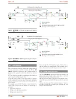
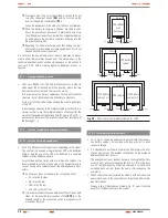
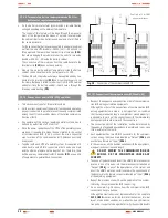
5.1.4.6. Access to inside the cabinet for its connection.
• Any equipment and battery cabinet from
SLC CUBE3+
series
has terminals as connection elements for the power. Also UPSs
have a terminal strip for the auxiliary connections and HDB9 /
DB9 communication connectors.
To have access to them proceed as follows and repeat the same
procedure in each unit for parallel systems:
Unblock the lock/s
(CL)
by means of the key
(LL)
supplied
with the equipment, turn it to clockwise 45º.
Open the front door
(PF)
completely. DB9 connectors of
communication ports and terminals for EPO remote button
are visible.
Remove the screws
(t1)
that fix the terminal cover
(TB)
to
the cabinet and remove it; connection terminals are visible.
When finishing the UPS connection, put the cover
(TB)
back, fix it with the screws
(t1)
, close the door
(PF)
with
the key
(LL)
and lock
(CL)
.
Take into account the cross cable section, as regards to the
size of the own terminals of the switches, in order to embrace
all their section properly for an optimal contact between both
elements.
USER MANUAL


