43
SALICRU
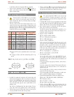
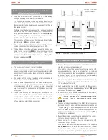
5.2.8. EPO terminals (X50).
• All UPSs have two terminals to install an external emergency
button to shutdown the output (EPO).
• In case it was required to install a switch or button (EPO) in a
single equipment, the cable bridge that closes the circuit has to
be removed from terminal strip
(X50)
first.
• For a parallel system, two different solutions can be applied,
which are the following:
Connect the button (EPO) in only one equipment of the par-
allel system. Remove the cable bridge from terminals
(X50)
in the equipment that it is only connected.
In case of fault and removing of the equipment that has
physically connected the button (EPO), there is the risk of
leaving the system without the emergency stopping, unless
it is reconnected to the other operative UPSs.
Connect a button (EPO) to each equipment of the parallel
system. To do that, remove all the cable bridges from termi-
nals
(X50)
in each equipment.
Therefore, the functionality of the (EPO) will be kept in each
one of them, regardless what occurs in the rest of equip-
ments of the parallel system.
By means of the own communication BUS among the equip-
ments that make the parallel system, any action over any button
will affect to the whole.
• In any case, the switch or button (EPO) has to be normally closed
(NC), so the emergency shutdown order will be triggered when
opening the circuit between these terminals
(X50)
.
To restore the UPS to normal mode, invert the position of the
switch or button (EPO), -close the circuit between the terminals
(X50)
-, unblock the button.
• To know the operating of (EPO), see section 6.6. of this manual.
• The base of front door
(PF)
has a slot to facilitate the entering and
way out of the communication cables inside the UPS. Watch to not
trap them between the door and cabinet when closing it.
(X50)
EPO
(Output
Emergency
Shutdown)
Fig. 37.
Connection terminals for emergency shutdown switch or
button (EPO), belonging to the end/user.
5.2.9. Auxiliary contact and battery temperature probe
terminal strip.
• All the equipments are provided with terminal strip that cor-
responds to the auxiliary contacts of manual bypass
(X51)
and
output
(X45)
switches.
• Also in the equipments either with separate battery cabinet
(models >20 kVA (LV) / >40 kVA (HV)) or in B1 equipments,
the additional terminal strip
(X34)
are supplied, to connect the
battery temperature probe that allows compensating the floating
voltage according to the ambient temperature.
• Any wire connected to the terminals
(X34)
,
(X45)
and
(X51)
, will
be entered into the equipment through the cable bushing
(PR)
.
5.2.9.1. Terminal strip, auxiliary contact of manual bypass
switch (X51).
• Terminal strip
(X51)
of two pins of the UPS, is connected in par-
allel with the normally opened auxiliary contact of the switch or
manual bypass switch of the equipment.
• Switchgear panel board with manual bypass manufactured by
us (option), there is a terminal strip of two terminals connected
in parallel with the normally opened auxiliary contact of the
switch or manual bypass switch of the own switchgear panel
board. Any auxiliary contact of the manual bypass are moved on
in advance when closing.
•
In case of acquiring a switchgear panel board
with manual bypass in another way, check that it
has the stated auxiliary contact and connect it to the
terminal strip (X51) of each equipment. As a must, the
auxiliary contact has to be moved on in advance when
closing.
•
It is
ESSENTIAL
as safety measure of the system,
loads included, to connect the terminal strips
(X51)
of
the UPSs with the terminal strip with the same functionality of
the switchgear panel board.
This way, any wrong action
over any switch or manual bypass switch of the turned
on UPSs will avoid causing a total or partial fault of the
installation, loads included.
5.2.9.2. Terminal strip, auxiliary contact of output switch
(X45).
• This terminal strip of two pins is available in any equipment, but
it is useful in parallel systems only.
• Basically, the normally opened auxiliary contact of the output
switch, is extended till the terminal strip of two pins
(X45)
.
Through the isolated cable as a bridge mode that is supplied
connected between both pins, the circuit is closed. Do not re-
move in single equipments, because although the equipment
would be in operation, there would be an alarm of output switch
deactivated.
• In those installations with parallel systems, the cable as a bridge
mode connected between the two pins of the terminal strip
(X45)
of each UPS has to be removed, and connected to the ter-
minals corresponding to the auxiliary contact of the output switch
of the switchgear panel board.
•
In case of acquiring a switchgear panel board by
yourself, check that the output auxiliary contact
is available and connect it to the terminal strip (X45) of
each equipment. As a must, the auxiliary contact has to
be moved on in advance when opening.

