


57
SALICRU
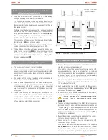
NOT AVAILABLE measurement screens according to UPS setting.
(III / III)
-N- (III / I)
-L- (I / I)
-M- (I / III)
-
-
2.1
2.1
-
-
2.13
2.13
-
-
2.14
2.14
-
-
2.15
2.15
-
-
2.16
2.16
-
-
2.17
2.17
-
-
2.18
2.18
-
2.21
2.21
-
-
2.22
2.22
-
-
2.23
2.23
-
-
2.24
2.24
-
-
2.25
2.25
-
-
2.26
2.26
-
-
2.29
2.29
-
In case of being a frequency converter, a part from the NOT
AVAILABLE screens according to the setting, the following
ones will not be available too:
Converter with batteries: 2.7 and 2.8.
Converter with no batteries: 2.7, 2.8, 2.10, 2.11, 2.12 and
2.33.
Tabla 5.
NOT AVAILABLE measurement screens according to
the UPS setting.
•
Screen 2.1
: input voltages phase to phase (units 0.1 V).
•
Screen 2.2
: three phase input voltages phases to neutral or for
single phase input phase to neutral (units 0.1 V).
•
Screen 2.3
: input current per each phase for three phase
equipments or for the phase for single phase equipment (units
0.1 A).
•
Screen 2.4
: three phase output voltages phases to neutral, or
for single phase output phase to neutral (units 0.1 V).
•
Screen 2.5
: output current per each phase for three phase equip-
ments or for the phase for single phase equipment (units 0.1 A).
•
Screen 2.6
: three phase inverter output voltages phases to neutral,
or for single phase inverter output phase to neutral (units 0.1 V).
•
Screen 2.7
: three phase bypass voltages phase to neutral or for
single phase bypass phase to neutral (units 0.1 V).
•
Screen 2.8
: bypass current per each phase for three phase
equipments or for the phase for single phase equipment (units
0.1 A).
•
Screen 2.9
: positive and negative DC bus voltages (units 0.1 V).
•
Screen 2.10
: positive and negative battery voltages (units 0.1 V).
•
Screen 2.11
: positive and negative battery charging currents
(units 0.1 A).
•
Screen 2.12
: positive and negative battery discharging cur-
rents (units 0.1 A).
•
Screen 2.13
: input apparent power of L1 (units 0.1 kVA).
•
Screen 2.14
: input apparent power of L2 (units 0.1 kVA).
•
Screen 2.15
: input apparent power of L3 (units 0.1 kVA).
•
Screen 2.16
: input active power of L1 (units 0.1 kW).
•
Screen 2.17
: input active power of L2 (units 0.1 kW).
•
Screen 2.18
: input active power of L3 (units 0.1 kW).
•
Screen 2.19
: total input apparent power and active power
(units 0.1 kVA and 0.1 kW).
•
Screen 2.20
: input power factor of each phase in three phase
equipments or input power factor for single phase equipments
(units 0.01).
•
Screen 2.21
: apparent output power of L1 (units 0.1 kVA).
•
Screen 2.22
: apparent output power of L2 (units 0.1 kVA).
•
Screen 2.23
: apparent output power of L3 (units 0.1 kVA).
•
Screen 2.24
: active output power of L1 (units 0.1 kW).
•
Screen 2.25
: active output power of L2 (units 0.1 kW).
•
Screen 2.26
: active output power of L3 (units 0.1 kW).
•
Screen 2.27
: total apparent and active powers (units 0.1 kVA
and 0.1 kW).
•
Screen 2.28
: output power factor of each phase for three
phase equipments or output power factor for single phase
equipments (units 0.01).
•
Screen 2.29
: total load of three phases (units 0.1%).
•
Screen 2.30
: total input and output load (units 0.1%).
•
Screen 2.31
: input, bypass and output frequencies (units 0.1 Hz).
•
Screen 2.32
: rectifier, inverter and battery temperatures (units 1 ºC).
•
Screen 2.33
: estimated backup time (units 1 minute).
Displayed measurements in screens 2.1 to 2.8, 2.20, 2.28 and
2.29 will be according to the input and output topologies,
depending if they are single phase (there will be one figure only in the
LCD panel) or three phase (there will be three figures that correspond
to the three phases).
7.3.4. ‘‘PARAMETERS’’ level (screen menu 3.0). See fig 47.
•
Screen 3.1
: In the first row, the time “hh:mm:ss” (hours/min-
utes/seconds) can be set and in the second row the date “dd/
mm/yy” (day/month/year) can be set.
•
Screen 3.2
: In the first row, the display language can be se-
lected among the following options:
“Spanish”
“English”
“French”
“German”
“Turkish”
“Russian”
In the second row, the Modbus Address can be set. The range
of addresses goes from 1 to 247.
•
Screen 3.3
: This screen allows setting the BAUD RATE of com-
munication port #0. The available options are the following:
“1200”
“2400”
“4800”
“9600”
“19200”


