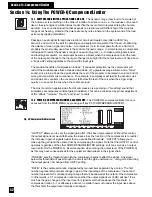
"DLY
" and "DLY
" enable adjustment of the digital delay time for channel A or B. Delay is
adjusted using soft key #1 to increase delay and soft key #2 to decrease. Channels A and B
delays can only be set independently of each other.
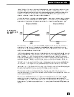
13.3 USING THE POWER-Q RTA AND DIGITAL DELAY SETTINGS TO MINIMIZE COMB FILTERS.
Comb filters
arise in any acoustical setting where direct and reflected sounds (or two or more speakers playing
the same sound source) combine in equal, or near-equal, amplitude (i.e., are close to the same
volume). Slight delays in the arrival of sounds at a particular location in an acoustic environment
will cause a phase interference pattern. Some frequencies will be attenuated, while others will be
reinforced, producing a frequency response showing many “peaks and valleys” and also resem-
bling the teeth of a comb (see Figure 8 on page 15). The specific frequencies that are boosted or
cut will depend on the physical layout of the acoustical space and the location of the speakers and
your reference listening position. The attenuated frequencies will be heard at a lower volume,
and the reinforced frequencies will be emphasized and are prone to feedback.
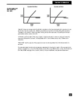
Unfortunately, equalization cannot cure comb filtering. However, digitally delaying the arrival of
some of the sound creating the phase interference pattern can minimize the comb filters. You can
experiment with the digital delays in the POWER-Q while analyzing pink noise as heard at the
reference microphone, and observe the results. Here’s a step by step guide to this comb-filter
minimization procedure:
• Make sure your system is set up correctly and passing audio signal properly. Make sure your
two speakers pass signal at equal volume. (NOTE: The steps described here will apply to a
system with two or more speakers or speaker stacks aimed at the audience.)
• Set your reference microphone up at an appropriate listening spot. To maximize the potential
for comb filtering, the microphone should be close to equidistant from the two speakers (to
hear the sound from the speakers at equal volume).
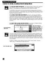
• From the MAIN MENU, select option #4 (“REAL-TIME ANALYZER”). Select “REF” at soft
key #4 (this will display the RTA response of the reference microphone). Then press the
“MORE” button 3 times to reveal the screen in Fig. 48 on page 40
of this manual.
• Press soft key #3 (“NOISE”). The NOISE GENERATION OPTIONS screen (Fig. 45, page 39)
will appear. Set the gain of the noise generator to the desired setting, then select “PINK in
A&B” and hit ENTER. This will play pink noise through both speaker stacks.
• While observing the RTA as heard by the reference microphone, experiment with delays in
both channels A and B until the comb filtering is minimized, i.e., the frequency response as
heard by the reference microphone shows minimal peaks and valleys.
• When you’re satisfied your comb filtering is minimized, proceed with equalization.
13.4 USING THE POWER-Q RTA DURING PERFORMANCE
The POWER-Q RTA need not be used only as
a setup tool. It can also be employed as a visual aid when mixing live or recorded sound. If the
reference microphone is set up and feeding the RTA input during performance, you will see a
frequency map of the sound energy emanating from the speakers, as heard at the reference mic.
Superimposed on top of the RTA you will see the graphic EQ sliders in the positions you have set
them.
The RTA may prove useful in the following ways:
• During sound check, when it is possible to use the mixing console’s “Solo” function, or by
using an auxiliary bus during performance, it is possible to analyze the frequency map of an
individual voice or instrument with the POWER-Q RTA. This may show useful frequency
information for optimizing an input’s EQ using the console’s equalizer controls on the
appropriate channel.
• During performance, when the entire audio output of the console is routed through the
POWER-Q, you will see the audio program's frequency map. This may help you determine
a proper frequency balance of the overall mix using POWER-Q graphic EQ controls.
• If feedback arises during sound check or performance, the swelling frequency of the
feedback will be apparent on the RTA, thus indicating the frequency to attenuate in order to
remove the feedback. (The POWER-Q FBX feature will do this for you automatically.)
Section 13: RTA
41
1


