Manual
Weld Seam Detection System R4000 SND40
for Tubes, Cans and Drums
B0059001 / Rev. 2.3
Mounting
ROLAND ELECTRONIC GmbH · Otto-Maurer-Str. 17 · DE 75210 Keltern · Phone +49 (0)7236-9392-0 · Fax +49 (0)7236-9392-33
31
3.2
Mounting of Eddy Current probes
Basically, an eddy current probe can be mounted in any orientation. However, an overhead
mounting (probe face looking down) is favourable, since the probe will be less contaminated.
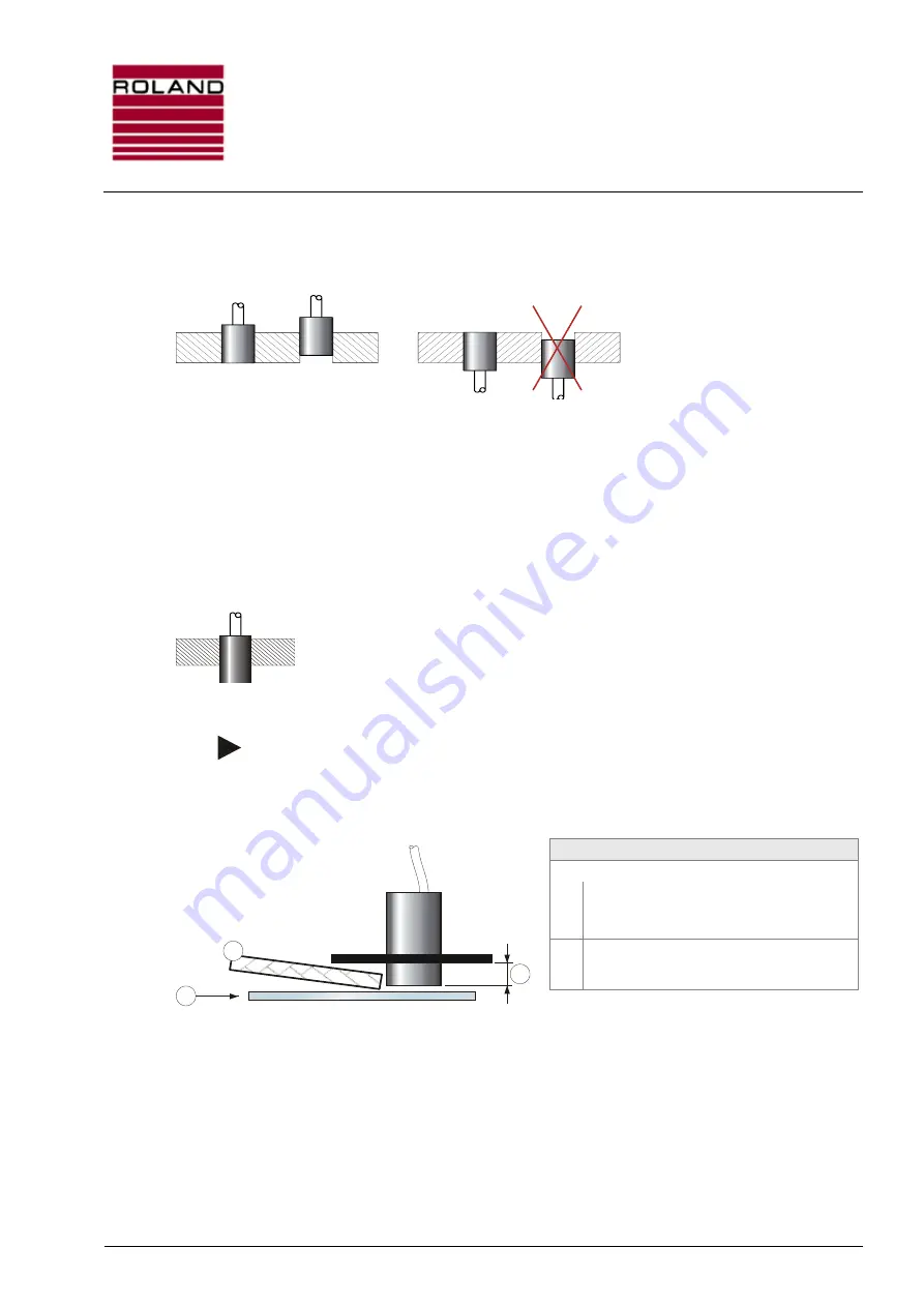
Fig. 11: Mounting of Eddy Current probes
The probe may be mounted flushed or recessed only in rigid plastic, ceramics or other non-
conductive materials.
A recessed mounting protects the probe, but increases the air gap between material and probe.
Furthermore, particles and scarfs can accumulate in the recess, which also can reduce the
measuring capacity. Thus, mount the probe recessed only in overhead orientation.
Has the sensor been mounted in a holder with high electrical connectivity (e.g. Aluminium), then
this material will extract energy from the sender in form of eddy current. This reduces the capability
of the probe.
Non-flushed (standing-out) mounting can also be done in metallic holders.
Then care for an utmost large distance between the active side of the sensor
and the holder.
Fig. 12: Standing-out mounting of EC probes
Note:
When the probe is mounted in a holder made of steel, the probe should look of the
holder for at least 10 mm. This can necessitate that the probe must be protected
from damage by additional baffles.
Legend
1:
Steel holders: Let the probe look out of the
holder for more than 10mm.
Plastic holders: Flushed mounting is practical.
2:
External baffle
3:
Transport direction of material
Fig. 13: Mounting of external baffles
Depending on the kind of probe, the correct distance between probe and material surface is at
0.3 ...1mm.
The smaller the probe is, the smaller the correct distance is.
Since the distance between probe and material must be kept constant, it is essential to guide the
probe on the material. Exception: the distance remains constant due to material guidance.
While measuring, the rear side of the material must be free from any metallic matter (especially
support rollers, tapered guidance or mandrels), since this influences the measuring.
Structural irregularities (e.g. holes or grooves) will cause very strong interference signals.
1
2
3


