background image


Manual 

Double Sheet Control System R1000-Series L20 

with integrated fieldbus interface 


Double Sheet Control-System 


L20 


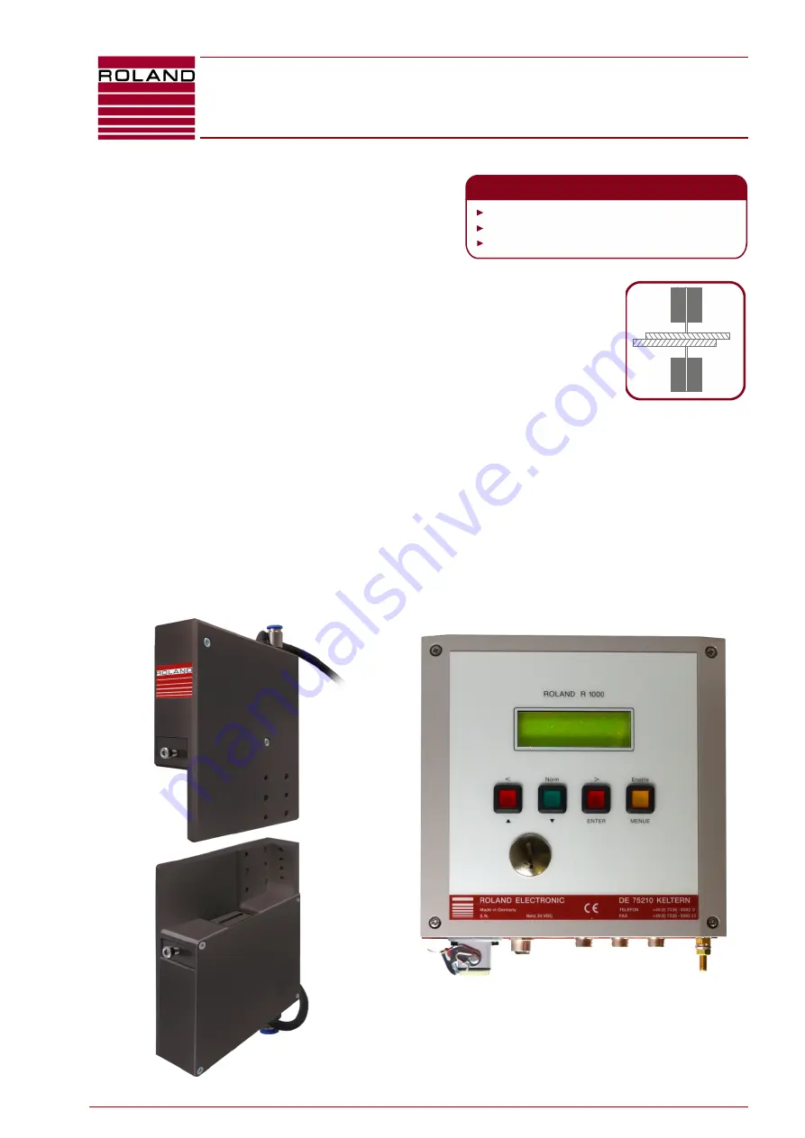
Dual Head Double Sheet Control System  
for Metals and Non-ferrous metals  
Laser based Function principle


Thickness Control from 0.3 to 15 mm 


Up to 3 pairs of sensors can be connected to the control unit (3 channel version)


Suitable for magnetic feeder systems without velocity limitation


Absolute measuring method 


Digital display of sheet thickness and operational parameters 

  Monitoring of over-gauge and under-gauge limit 

  Integrated fieldbus interface with process and parameter interface 


THE ROLAND PLUS:

All common Fieldbus standards

Maintenance-free

For composite materials also

Содержание l20

Страница 1: ...to 15 mm Up to 3 pairs of sensors can be connected to the control unit 3 channel version Suitable for magnetic feeder systems without velocity limitation Absolute measuring method Digital display of...

Страница 2: ...Str 17 75210 Keltern Germany All rights on this document are at ROLAND ELECTRONIC GmbH Reproduction also partly electronical coverage translation transmission to third parties only with our prior per...

Страница 3: ...ement principle 12 3 2 Control unit 14 4 Mounting 17 4 1 General mounting instructions 17 4 2 Dimensions of the system 18 4 3 Mounting of sensors 19 5 Electrical installation 25 5 1 General instructio...

Страница 4: ...h calibration sheet faults 105 9 7 Measuring channel calibration faults 105 9 8 Hardware faults 105 9 9 Supply voltage faults 105 9 10 Sensors Sensor cables faults 106 9 11 Other faults 107 10 Mainten...

Страница 5: ...onic GmbH declares that the product listed above complies with the requirements of the EMC directives listed below Applied Directives 2006 95 EG Low Voltage Directive EN61010 1 2010 2004 108 EG EMC Di...

Страница 6: ...ouble Sheet Control System R1000 series L20 with integrated fieldbus interface B0063191 1 3 6 ROLAND ELECTRONIC GmbH Otto Maurer Str 17 DE 75210 Keltern Phone 49 0 7236 9392 0 Fax 49 0 7236 9392 33 Bl...

Страница 7: ...g in case of service or repair to make measurements within the unit then all customary accidents prevention procedures should be observed Only professional electrical tools should be used Note The fa...

Страница 8: ...of not detecting a double sheet The following external factors decisively influence the stability of measuring results and need to be considered for operation of a double sheet detector Optical chara...

Страница 9: ...al supply Specification min switching voltage HIGH 13 VDC min switching voltage LOW 0 VDC max switching voltage HIGH 30 VDC max switching voltage LOW 8 VDC 5 potential free outputs with positive exter...

Страница 10: ...acy 0 05 mm Measuring principle Laser triangulation Laser Class 2 EN 60825 1 Class of protection IP54 Weight approx 2 2 kg 4 85 lbs without mounting angle and alignment aid Material of enclosure Alumi...

Страница 11: ...s based on the product platform R1000 and consists of three components the control unit one to three sensor systems each with two sensors and brackets sensor cables Fig 1 System L20 LAS40 LAS40 LAS40...

Страница 12: ...e 3 1 1 Planning information for mechanics The total distance Ax of both sensors from each other has a great influence on the measurement precision Important An appropriate stable and rigid mechanism...

Страница 13: ...and 0 7mm For safe operation the upper limit must be set to 0 45mm 150 of the nominal thickness and the lower limit to 0 15 mm 50 of the nominal thickness If the limits 150 respectively 50 are not su...

Страница 14: ...al via PLC 3 The sensors are well accessible for cleaning Normally the air blow off is sufficient to allow reliable operation in vicinity of oiling However failure of air blow off can cause serious co...

Страница 15: ...omer requirements can be served Configuration is performed by setting system parameters adjust parameters and program parameters System parameters are set only once during commissioning and will then...

Страница 16: ...ent values Implementation Restrict the 1 sheet area This is done by decreasing the low value and or increasing the up value 2 Target Keep the system function alive despite fluctuating measuring values...

Страница 17: ...uences on the operation 4 1 General mounting instructions The enclosure for wall mounting meets IP65 and is designed for mounting the enclosure close to the sensor location By using short sensor cable...

Страница 18: ...DE 75210 Keltern Phone 49 0 7236 9392 0 Fax 49 0 7236 9392 33 4 2 Dimensions of the system 4 2 1 Dimensions of the unit in industrial enclosure 1 channel unit L20 XX S and 3 channel unit L20 3 XX S F...

Страница 19: ...For this purpose Roland Electronic provides the bracket SHLAS40H which allows easy alignment not shown The sensors provided within the sensor system LAAS40 have already been aligned using the bracket...

Страница 20: ...ment bracket tight The screws may be screwed in this case depending on the mounting situation from both sides in order to be easily removed after the alignment Thereby make sure that the sensors lay p...

Страница 21: ...les Fig 9 Position of the sheet between the sensors 4 3 5 Sensor gaps The gap between the sensors is derived from the sensor name in mm The sensor LAAS40 has a gap of the sensors of 40 mm with a toler...

Страница 22: ...irect proximity of equipment which emits electromagnetic interference The sensor cables should not be laid adjacent to conductions having a large disturbance potential e g power cables This applies es...

Страница 23: ...therefore no longer guaranteed To disconnect the hose use an 8 mm or 9 mm open ended wrench as shown in Fig 6 right For the supplied purging air there are requirements regarding purity and freedom fro...

Страница 24: ...urer Str 17 DE 75210 Keltern Phone 49 0 7236 9392 0 Fax 49 0 7236 9392 33 The service unit consists of On off valve HE D Mini 170681 Filter regulator unit LFR 1 8 DB 7 0 Mini 537651 Micro filter LFA D...

Страница 25: ...he receptacle These items are designed to prevent incorrect connecting positions For this reason if plug and receptacle are connected together then these positioning features should fit to each other...

Страница 26: ...minals are at the front plate 1 the fieldbus connections are specific to each type of fieldbus Fig 13 Connections at the L20 3 XX S 5 2 2 Configuration of connectors at L20 3 XX S Legend X1 Connection...

Страница 27: ...cable plug contacts is part of the standard scope of supply Note Pin 6 is connected with pin 7 of connection X2 Pin 7 is connected with pin 1 of connection X2 Note The cable for the voltage supply sh...

Страница 28: ...er outputs for fast switching operation For reasons of velocity and for diagnostic purposes it could be useful to issue the relevant switching signal 0 sheet 1 sheet 2 sheet via a real time interface...

Страница 29: ...connector at control unit M12 5 pin A coded female connector at control unit View plug side Pin 1 Shield View plug side Pin 2 V Pin 3 V Pin 4 CAN High Pin 5 CAN Low Suppliers types notes Binder type 7...

Страница 30: ...iew Plug side Pin 1 TD Pin 2 RD Pin 3 TD Pin 4 RD Plug enclosure Shield 5 2 5 6 CC Link The protocol version 1 of CC Link is supported An M12 plug with A coding is used for the CC Link connection A T...

Страница 31: ...IN Connection X4 OUT Connection X3 View Plug side Pin 1 TD Pin 2 RD Pin 3 TD Pin 4 RD Plug enclosure Shield 5 2 6 Connection of earth ground Connection X5 For earth ground connection the enclosure of...

Страница 32: ...control unit by plug All sensors require this cable type Note When using the sensor system LAAS40 the connection of the sensor system with the sensor cables to the terminals A and B is arbitrary If th...

Страница 33: ...3 Electrical installation ROLAND ELECTRONIC GmbH Otto Maurer Str 17 DE 75210 Keltern Phone 49 0 7236 9392 0 Fax 49 0 7236 9392 33 33 5 2 10 Beam control connection Connection C The sensor cable SC5M1...

Страница 34: ...ontrol System R1000 series L20 with integrated fieldbus interface Electrical installation B0063191 1 3 34 ROLAND ELECTRONIC GmbH Otto Maurer Str 17 DE 75210 Keltern Phone 49 0 7236 9392 0 Fax 49 0 723...

Страница 35: ...ibus DP 4 Bus status 5 Parameter channel status 6 Bus slave address only if Fieldbus with node bus address 7 Fieldbus baud rate only if Fieldbus with baud rate or MAC ID Fig 15 Fieldbus specific messa...

Страница 36: ...lication data byte 1 BIN5 Application data byte 2 BOUT5 Application data byte 2 BIN6 Application data byte 3 BOUT6 Application data byte 3 BIN7 Checksum BOUT7 Checksum Process channel BIN8 Control BOU...

Страница 37: ...3 BIN10 4 BOUT10 4 BIN10 5 BOUT10 5 BIN10 6 BOUT10 6 BIN10 7 BOUT10 7 BIN11 0 BOUT11 0 Low Byte measuring value 4 Measuring channel 1 BIN11 1 BOUT11 1 BIN11 2 BOUT11 2 BIN11 3 Dummy Function 3 BOUT11...

Страница 38: ...BIN14 0 BOUT14 0 Low Byte measuring value 4 Measuring channel 1 BIN14 1 BOUT14 1 BIN14 2 BOUT14 2 BIN14 3 Dummy function 3 BOUT14 3 BIN14 4 Dummy function 3 BOUT14 4 BIN14 5 BOUT14 5 BIN14 6 BOUT14 6...

Страница 39: ...T16 5 BIN16 6 BOUT16 6 BIN16 7 BOUT16 7 BIN17 0 BOUT17 0 Low Byte measuring value 4 Measuring channel 2 BIN17 1 BOUT17 1 BIN17 2 BOUT17 2 BIN17 3 Dummy function 3 BOUT17 3 BIN17 4 Dummy function 3 BOU...

Страница 40: ...BOUT20 1 BIN20 2 BOUT20 2 BIN20 3 Dummy function 3 BOUT20 3 BIN20 4 Dummy function 3 BOUT20 4 BIN20 5 BOUT20 5 BIN20 6 BOUT20 6 BIN20 7 Range only L20 3 XX S BOUT20 7 2 For the outputs 0V active or 2...

Страница 41: ...will not be displayed The other outputs remain in their current status If the fault occurs during execution the Function fault is displayed The Function result will not be displayed if the fault is c...

Страница 42: ...bus BOUT8 4 7 with a refresh rate of 6 ms Through the I O outputs OUT the rate is 1 ms Note The output Function result is set with the appearance of the first measurement value and then remains set No...

Страница 43: ...ily set Note The measured timing periods were determined with12 Mbit s Profibus These timing periods can vary with different transmission rates and bus systems The cycle time of the PLC has not been t...

Страница 44: ...test no sheet is allowed to remain between the sensors Fig 19 Timing diagram for system test 1 In case of Function fault Function result is not necessarily set L20 3 XX S with LAAS40 55 ms L20 3 XX S...

Страница 45: ...t 6 3 7 Calibration static L20 XX S only A static calibration is not possible with L20 3 XX S L20 XX S is in preparation Fig 21 Timing diagram for calibration static Note The measured timing periods w...

Страница 46: ...each In 1 sheet dynamic Note The measured timing periods were determined with 12 Mbit Profibus These timing periods can vary with different transmission rates and bus systems The cycle time of the PLC...

Страница 47: ...e of the PLC has not been taken into account 6 3 10 Reset Function fault Fig 24 Timing diagram for reset function fault 1 In case of Function fault Function result is not necessarily set BOUT8 3 is no...

Страница 48: ...Byte Meaning Parameter channel BIN0 Management BOUT0 Management BIN1 Program index BOUT1 Program index BIN2 Parameter index BOUT2 Parameter index BIN3 Application data byte 0 BOUT3 Application data by...

Страница 49: ...awal of the faulty service BOUT0 6 Handshake The state is changed with every new job It is controlled by the master only when a new job is to be processed by the R1000 The R1000 mirrors the handshake...

Страница 50: ...ata transmission Note If reading cannot be executed the collision bit is set The fault number is transmitted instead of application data bit see section 6 4 8 Reset faulty access The collision bit can...

Страница 51: ...00 in order to avoid data faults The slave should ensure a consistent data transmission Note A collision bit is et if reading cannot be executed Instead of application data the default number is trans...

Страница 52: ...ors the index adjustment in BOUT1 BOUT2 and the application data in BOUT3 BOUT6 A possibly set collision bit is set back Only in the last step inserts the R1000 the handshake bit in BOUT0 0 and indica...

Страница 53: ...ove can prevent the service execution during reading or writing The R1000 indicates this problem by the collision bit In order to prevent an additional uncontrolled access procedure the R1000 expects...

Страница 54: ...the service Empty service remove the cause of the collision and open again If necessary evaluate fault number in application data byte 5 Set the upper limit to the desired program index e g program n...

Страница 55: ...pler input 1 24 V active IN1 Measurement start input 2 Optocoupler input 2 24 V active IN2 Measurement start input 3 Optocoupler input 3 24 V active The Measurement start inputs are linked in differen...

Страница 56: ...s reset then a fault has occurred which requires a user intervention at the control unit Possible causes memory faults missing or too low voltages Note The timing diagrams in the sections 6 5 3 and 6...

Страница 57: ...or external single measuring via external inputs 1 At function error the function result not set mandatory 2 The measuring time depends on the time set for averaging Note The operation of the individu...

Страница 58: ...ement external special via external inputs 1 At function error the function result not set mandatory 2 The measuring time depends on the time set for averaging The status of the 0 1 2 sheet and warnin...

Страница 59: ...e are for example the Siemens step 7 tools Roland Electronic does not supply such tools because they have to be compatible with the interface design of the master The GSD file is supplied on a CD or c...

Страница 60: ...such tools because they have to be compatible with the interface design of the master The EDS file is supplied on a CD or can be downloaded from the Roland homepage Note 24 Bytes I O must be set By p...

Страница 61: ...le with the interface design of the master The EDS file is supplied on a CD or can be downloaded from the Roland homepage Note 3 PDOs with 8 Bytes each are set By pressing the key status indicators ar...

Страница 62: ...t By pressing the key status indicators are shown on the display Status Indicators Nr LED State Description LED 1 Link Activity Green Link established Green flashing Receiving Transmitting data Off No...

Страница 63: ...rd Data area word 4 to 11 not used Bit 3 Remote Ready 1 Roland L20 Parameter channel see Chapter 6 4 Roland L20 Process channel see Chapter 6 3 Link Output PLC Roland R1000 W0 W1 W2 W3 W4 W5 W6 W7 W8...

Страница 64: ...atus indicators are shown on the display Status Indicators Nr LED State Description LED 1 Link Activity LED configuration 1 Default Off Link not sensed Green Link sensed LED 2 Module Status LED config...

Страница 65: ...es I O must be set By pressing the key status indicators are shown on the display Status Indicators Nr LED State Description LED 1 Link Activity 1 Off No link sensed on Ethernet port 1 Green Link sens...

Страница 66: ...ntrol System R1000 series L20 with integrated fieldbus interface Communication with the PLC B0063191 1 3 66 ROLAND ELECTRONIC GmbH Otto Maurer Str 17 DE 75210 Keltern Phone 49 0 7236 9392 0 Fax 49 0 7...

Страница 67: ...d before applying power The control unit is automatically switched on by applying the power After applying power the type of system and the version number are briefly displayed If the system does not...

Страница 68: ...switched off 1 LED functions 2 Pushbutton functions 3 Program number 4 Nominal thickness 5 State of measurement 6 Lower limit value 7 Upper limit value 8 Measured value of measuring channel 1 9 Measu...

Страница 69: ...th integrated fieldbus interface B0063191 1 3 Start up ROLAND ELECTRONIC GmbH Otto Maurer Str 17 DE 75210 Keltern Phone 49 0 7236 9392 0 Fax 49 0 7236 9392 33 69 7 4 Configuration menu 7 4 1 Main menu...

Страница 70: ...h integrated fieldbus interface Start up B0063191 1 3 70 ROLAND ELECTRONIC GmbH Otto Maurer Str 17 DE 75210 Keltern Phone 49 0 7236 9392 0 Fax 49 0 7236 9392 33 7 4 2 Sub structure program parameters...

Страница 71: ...th integrated fieldbus interface B0063191 1 3 Start up ROLAND ELECTRONIC GmbH Otto Maurer Str 17 DE 75210 Keltern Phone 49 0 7236 9392 0 Fax 49 0 7236 9392 33 71 7 4 3 Sub structure system adjustment...

Страница 72: ...0063191 1 3 72 ROLAND ELECTRONIC GmbH Otto Maurer Str 17 DE 75210 Keltern Phone 49 0 7236 9392 0 Fax 49 0 7236 9392 33 7 4 4 Sub structure system parameters details in 7 9 Fig 33 Sub structure system...

Страница 73: ...blinking in the display The selected set parameters are activated by pressing the ENTER key Note The systems info and bus info is displayed by pressing the ENTER key in the base menu also see system p...

Страница 74: ...r exiting the configuration mode the password remains active for five minutes Thus other configuration adjustments can be made without re entering the password If no key is pressed for five minutes wh...

Страница 75: ...For L20 XX S not available For L20 3 XX S Fig 39 Selecting the active measuring channel At this point select the active measuring channel used during the measuring operation Possible choices are 1 2 3...

Страница 76: ...he upper limit value Fig 42 Adjusting the upper limit Value range between 100 and 180 of the nominal value with simultaneously displaying the absolute limit value Program parameter 7 Adjusting the tim...

Страница 77: ...is valid to all programs Note LAAS10 LAAS10 and LAAS200 LAAS200 are in preparation Fig 44 Selection of measuring channel Display missing Measuring channel calibration at one measuring channel has not...

Страница 78: ...Occurring fault messages read section 9 Fault messages Now the rated sensor range is shown The margin areas must be avoided Fig 47 Showing of the rated sensor range If several measuring points have b...

Страница 79: ...ibration is advantageous because localized thickness variations or fluctuations in the calibration piece will have less impact on the calibration L20 XX S L20 3 XX S The deviation is shown as a result...

Страница 80: ...heet has to be inserted Fig 52 Display of the calibration deviation Pressing the ENTER key will close the display of the calibration deviation For L20 3 XX S Adjustment parameter 4 System test Alignme...

Страница 81: ...ignment of the sensors borderline 50 21 Explanation the alignment of the sensors should be verified because it is not optimal Remove any contamination from sensors if necessary bad 20 0 Explanation th...

Страница 82: ...s makes a diagnostic possible L20 XX S L20 3 XX S Fig 58 Measured distance between the laser sensors At the L20 3 XX S the thickness D1 2 3 of the inserted sheet is displayed additionally Press the EN...

Страница 83: ...lace the paper between the sensors in the laser beam at different positions A larger displacement or an angular deviation of the laser beam causes at inclined positions of the sheet measurement deviat...

Страница 84: ...cessing select the system parameter configuration mode and confirm with ENTER System parameter 1 Setting the dialogue language Fig 61 Selecting the language Selectable languages English German Italian...

Страница 85: ...AAS10 LAAS40 and LAAS40 0 0001 inch or 0 001mm LAAS200 and LAAS200 0 001 inch or 0 01mm LAAS10 LAAS10 LAAS200 LAAS200 are in preparation System parameter 5 Setting the display time Fig 65 Setting the...

Страница 86: ...ed here Fig 68 Setting IP Address The SubNet can be selected here Fig 69 Setting SubNet The Gateway can be selected here Fig 70 Setting Gateway System parameter 7 Indicating of the the Bus baud rate F...

Страница 87: ...g the password on off Selectable options yes no Attention If password protection is not activated then all parameters can be accessed at any time This is recommended only during starting up the system...

Страница 88: ...e of sensor Selectable options LAAS10 in preparation LAARS10 do not use LAAS10 in preparation only for L20 3 XX S LAAS40 LAAS40 only for L20 3 XX S LAARS40 do not use LAAS200 in preparation LAAS200 in...

Страница 89: ...easurements as long as the Measurement start signal is applied external special As for external continuous but The highest value reached during a measurement cycle is displayed and maintained at the o...

Страница 90: ...timing diagrams and the wiring diagrams 24 V The outputs 0 sheet 1 sheet 2 sheet and warning are inverted i e the respective signals in the timing diagrams and wiring diagrams must be seen inverted N...

Страница 91: ...ust This setting has no influence Selectable options yes no System parameter 21 Monitoring the obstruction and measuring position Fig 85 Setting the internal system zeroing Selectable options no yes W...

Страница 92: ...UT d Process channel IN Parameter channel IN OUT Input PaI 00 00 00 00 00 00 00 00 Byte 0 1 2 3 4 5 6 7 Output PaO 00 00 00 00 00 00 00 00 Byte 0 1 2 3 4 5 6 7 0 stands for the outgoing data to the Fi...

Страница 93: ...al communication diagnose System parameter 26 not available System parameter 27 System info Fig 89 System info 1st line Display of the system type 2nd line Display of the versions of Software SV and H...

Страница 94: ...nel The secured data can then for example be transferred to an exchange substituted unit after a unit failure The data backup is accomplished with the RPP7 software available from ROLAND ELECTRONIC Th...

Страница 95: ...ower front panel USB slot with the PC Then select Firmware Update in the configuration mode Fig 92 Display for activating the firmware update After the USB terminal has been connected to the PC the fo...

Страница 96: ...Sheet Control System R1000 series L20 with integrated fieldbus interface Start up B0063191 1 3 96 ROLAND ELECTRONIC GmbH Otto Maurer Str 17 DE 75210 Keltern Phone 49 0 7236 9392 0 Fax 49 0 7236 9392...

Страница 97: ...g few exceptions The following situations require action directly at the control unit or an action via the PLC interface Clear fault and error messages see chapter 9 Error messages causes and remedies...

Страница 98: ...signal Fig 85 Clarification of the measuring time The measurement time tm is derived from the sum when operating via I O inputs the set time ta for averaging and an additional delay time of 5 ms for r...

Страница 99: ...switch to change with the key and confirm by pressing the ENTER key 3 Enter the password if active 4 Switch to adjustment parameter and confirm by pressing the ENTER key 5 At measuring channel calibr...

Страница 100: ...Sheet Control System R1000 series L20 with integrated fieldbus interface Operation B0063191 1 3 100 ROLAND ELECTRONIC GmbH Otto Maurer Str 17 DE 75210 Keltern Phone 49 0 7236 9392 0 Fax 49 0 7236 9392...

Страница 101: ...lt description and the suitable measures to remedy the fault condition are found in the following tables The cause of malfunction must be eliminated before the equipment can continue operation The fau...

Страница 102: ...d Store the value by pressing the ENTER key 12 System parameter 2 system type is not realistic 13 System parameter 5 display time is not realistic 14 System parameter 17 output 0 1 2 warning is not re...

Страница 103: ...tted Perform a Firmware update because system settings have been extended 9 3 System operation faults No Cause Remedy 51 Nominal thickness is 0 000 mm 0 0000 inch Enter correct nominal thickness 52 Me...

Страница 104: ...ic mode 78 The fieldbus function cannot be executed because the equipment detected double sheet with configuration double sheet hold Clear double sheet condition via fieldbus or via keyboard 79 The se...

Страница 105: ...placed between the sensors The sensors might be contaminated 151 Measuring channel 2 152 Measuring channel 3 153 Measuring channel 1 Timing PLC interface is faulty during calibration Check timing diag...

Страница 106: ...1 Sensor at connection A could not determine any gap while the same sensor determined a gap at connection B Check if Sensor A is contaminated Sheet to be measured is out of measuring window Further de...

Страница 107: ...l 3 Sensor for beam control defect 223 Measuring channel 1 Beam of sensor A not free Nothing must be between the sensors 224 Measuring channel 1 Beam of sensor B not free 225 Measuring channel 1 Beam...

Страница 108: ...System R1000 series L20 with integrated fieldbus interface Fault messages causes and remedies B0063191 1 3 108 ROLAND ELECTRONIC GmbH Otto Maurer Str 17 DE 75210 Keltern Phone 49 0 7236 9392 0 Fax 49...

Страница 109: ...r blow off for laser sensors 10 3 Device replacement Device replacement with RPP7 software The L20 permits backup of the equipment parameters with the provided RPP7 software via the USB interface virt...

Страница 110: ...se the USB Cable A Plug to A plug within scope of delivery Connect only one Roland device to a PC The drivers are included on the CD Switch the device to backup mode For details refer to chapter 7 10...

Страница 111: ...d Direction of data Management Program index Parameter index User data byte 0 User data byte 1 User data byte 2 User data byte 3 Check sum Range of values Read program parameters Measuring channel PLC...

Страница 112: ...erved 11h Reserved Save PLC L20 0H110010 12h 00h 00h 00h 00h XXh Attention This command will save the data 1 PLC L20 0H110010 12h 00h 00h 00h 00h XXh 1 With this command the data of the specified set...

Страница 113: ...00h 00h 00h 00h XXh PLC L20 0H110001 0Eh 00h 00h 00h LByte XXh 1 IN0 2 IN0 IN1 3 IN0 IN1 IN2 level 0 1 2 PLC L20 0H110001 0Fh 00h 00h 00h 00h XXh PLC L20 0H110001 0Fh 00h 00h 00h LByte XXh 0 0 V activ...

Страница 114: ...0010 03h 00h 00h 00h LByte XXh 0 mm 1 inch PLC L20 0H110010 03h 00h 00h 00h LByte XXh User data as sent Display time PLC L20 0H110010 04h 00h 00h 00h LByte XXh 0 20 0 0 0 sec 20 2 0 sec PLC L20 0H1100...

Страница 115: ...00h XXh 0 no ext adjustment 1 ext adjustment possible PLC L20 0H110010 10h 00h 00h 00h 00h XXh User data as sent Sensor type PLC L20 0H110010 11h 00h 00h 00h LByte XXh 0 LAAS10 1 LAARS10 or LAAS10 2...

Страница 116: ...t Control System R1000 series L20 with integrated fieldbus interface Technical records B0063191 1 3 116 ROLAND ELECTRONIC GmbH Otto Maurer Str 17 DE 75210 Keltern Phone 49 0 7236 9392 0 Fax 49 0 7236...

Страница 117: ...channel unit for one measuring channel Wall mount enclosure data backup via CanOpen USB port L20 3 CP S 3 channel unit for three measuring channels CC Link L20 CC S 1 channel unit for one measuring ch...

Страница 118: ...GG Superflex TRONIC C PUR UL 5 x 0 25 mm Connection cable for sensor LAS40 for laser beam monitoring at L20 both cable ends pluggable with straight cable plug at the unit and straight cable socket and...

Страница 119: ...__________ IP ________________ Subnet _______________ Gateway ________________ 9 Password active yes no 10 Password 0000 _________ 11 Measuring channels 1 2 3 only for L20 3 XX S 12 Sensor type only f...

Страница 120: ...eet Control System R1000 series L20 with integrated fieldbus interface Appendix B0063191 1 3 120 ROLAND ELECTRONIC GmbH Otto Maurer Str 17 DE 75210 Keltern Phone 49 0 7236 9392 0 Fax 49 0 7236 9392 33...

Отзывы: