Rockwell Automation Publication 1715-UM001J-EN-P - December 2020
97
Chapter 2 Installation Instructions
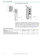
The adapter has four autosensing 10/100BASE-TX Ethernet ports for
connecting to a local area network through a minimum Cat5e shielded twisted
pair (STP) Ethernet cable. There are two ports for each adapter.
The adapter Ethernet ports are on the 1715-A2A adapter base unit and are
identified in this table.
The fixed connectors on the adapter are female RJ45 modular jacks. Use a
minimum Cat5e shielded twisted pair (STP) cable with male RJ45 modular
jacks for network cabling.
Connect the network cables to the sockets on the 1715-A2A adapter base unit.
To connect the adapter to the Ethernet network, follow these steps.
1. Insert the RJ45 modular jack on the cable into the appropriate socket for
each network connection.
2. Make sure that the length of the cable does not exceed 100 m (328 ft).
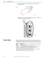
Module Keying
Module keying, or polarization, prevents the wrong module from being
inserted into the wrong base unit. Modules are supplied with coding pegs that
are already fitted, so the modules are already ‘keyed’.
Electronic Keying is used within the Logix Designer application. See
for more information.
IMPORTANT
The 1715 Redundant I/O System requires the use of a minimum
Cat5e shielded twisted pair (STP) Ethernet cable.
Table 11 - Allocation of 10/100BASE-TX Ports to Adapters
1715-AENTR Adapter
10/100BASE-TX Ports
Adapter A
A1, A2
Adapter B (where present)
B1, B2
IMPORTANT
Most network connections use straight-through cables.
Crossover cables are not needed due to the intelligence or
functionality of the switch. If a direct connection is required
from the adapter to the personal computer (for example, during
setup), it can be necessary to use a crossover cable. This
depends on the characteristics of the interface in the personal
computer.
32097 M
Содержание Allen-Bradley 1715-AENTR
Страница 10: ...10 Rockwell Automation Publication 1715 UM001J EN P December 2020 ...
Страница 114: ...114 Rockwell Automation Publication 1715 UM001J EN P December 2020 Chapter 2 Installation Instructions Notes ...
Страница 134: ...134 Rockwell Automation Publication 1715 UM001J EN P December 2020 Chapter 4 Digital I O Operation Notes ...
Страница 200: ...200 Rockwell Automation Publication 1715 UM001J EN P December 2020 Chapter 6 Configure the Redundant I O System Notes ...
Страница 244: ...244 Rockwell Automation Publication 1715 UM001J EN P December 2020 Chapter 9 Redundant I O System Diagnostics Notes ...
Страница 272: ...272 Rockwell Automation Publication 1715 UM001J EN P December 2020 Appendix C Reconfigure a Module Online Notes ...
Страница 290: ...290 Rockwell Automation Publication 1715 UM001J EN P December 2020 Appendix G History of Changes Notes ...
Страница 296: ...296 Rockwell Automation Publication 1715 UM001J EN P December 2020 ...
Страница 297: ...Rockwell Automation Publication 1715 UM001J EN P December 2020 297 Redundant I O System User Manual ...


