90
Rockwell Automation Publication 1715-UM001J-EN-P - December 2020
Chapter 2 Installation Instructions
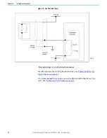
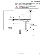
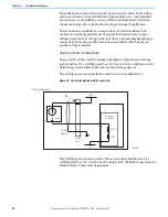
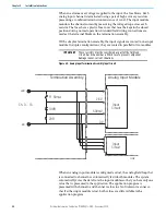
When an extreme over voltage is applied to the input, the fuse blows. Each
analog input channel is terminated using a pair of high accuracy resistors
presenting a combined termination resistance of 120 Ω. The input module
monitors the channel current by measuring the voltage drop across each
resistor. The fuses have a plastic fuse cover that must be kept in the closed
position during normal operation. Standard field wiring connections are
made at the terminal blocks on the termination assembly.
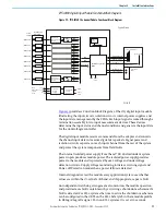
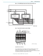
With a simplex termination assembly, the input signals are routed to one input
module. In duplex configurations, they are routed in parallel to two modules.
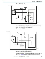
Figure 49 - Analog Input Termination Assembly Input Circuit
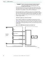
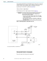
When an analog input module is configured as dual, the analog field loop that
is connected to channel 0 is automatically fed to both modules. The system
automatically votes the data from the input modules so that you have only one
value that is presented to the application. The application program is
presented with channel 0 and channel 1 values in a fault tolerant manner so
that if either input module is lost, both values are still available to the
application program.
IMPORTANT
These resistors must be considered as part of the field loop
circuit. Each channel has a 50 mA
fuse to prevent component
damage in over-current situations.
Input
Circuit
Input
Circuit
Ch. 0…15
+ve
F1 50 mA
100R
2.5V
500mV
0V
20R
-ve
Analog Input Module
Termination Assembly
32111 M
Содержание Allen-Bradley 1715-AENTR
Страница 10: ...10 Rockwell Automation Publication 1715 UM001J EN P December 2020 ...
Страница 114: ...114 Rockwell Automation Publication 1715 UM001J EN P December 2020 Chapter 2 Installation Instructions Notes ...
Страница 134: ...134 Rockwell Automation Publication 1715 UM001J EN P December 2020 Chapter 4 Digital I O Operation Notes ...
Страница 200: ...200 Rockwell Automation Publication 1715 UM001J EN P December 2020 Chapter 6 Configure the Redundant I O System Notes ...
Страница 244: ...244 Rockwell Automation Publication 1715 UM001J EN P December 2020 Chapter 9 Redundant I O System Diagnostics Notes ...
Страница 272: ...272 Rockwell Automation Publication 1715 UM001J EN P December 2020 Appendix C Reconfigure a Module Online Notes ...
Страница 290: ...290 Rockwell Automation Publication 1715 UM001J EN P December 2020 Appendix G History of Changes Notes ...
Страница 296: ...296 Rockwell Automation Publication 1715 UM001J EN P December 2020 ...
Страница 297: ...Rockwell Automation Publication 1715 UM001J EN P December 2020 297 Redundant I O System User Manual ...

