246
Rockwell Automation Publication 1715-UM001J-EN-P - December 2020
Appendix A Status Indicators
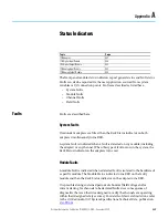
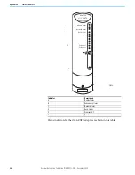
Channel Faults
A channel fault is indicated when a detected, faulty channel is isolated to a
hardware fault on a specific channel of an I/O module. All channel faults are
also reported as a module fault. This means that the CHANNEL indicator turns
RED, the Module Status indicator turns RED, and the Rack Status indicator on
the adapter also turns RED.
A channel fault on an input module indicates that the channel with the fault no
longer contributes to the reported values. In a dual configuration, as long as
one channel is not faulted, valid data continues to be reported.
If a channel fault on an output module occurs, the channel continues to drive
the output to the best of its ability, in most cases. Otherwise, a fail-safe state
occurs.
In dual configuration, the output values continue as determined by the
adapter as the second module outputs the full current.
It is possible during sustained periods of abnormal field voltage and/or
current slewing for channels to be declared faulted as a consequence of
diagnostics that are otherwise designed to verify the channels are operating
within their designed safety accuracy. For details of slew rate limitations, refer
to the 1715 Redundant I/O System Specifications Technical Data, publication
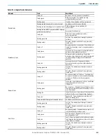
Field Faults
A field fault is indicated when a detected fault condition is isolated to a field
condition or field device and the cause is not the hardware that is associated
with the channel or output module. Examples are an open circuit field
connection, no field power, or an out-of-range signal. A CHANNEL indicator
flashing AMBER indicates these faults. Steady AMBER indicates that the
channel is ON or in range.
User Application Fault Indications and Logging
The information available includes the following:
•
Module presence (that is, Shutdown or Run modes)
•
Module health and status (that is, Module Status or Fault)
•
Channel health and status (that is, individual channel Module Status/
fault or field fault)
•
An echo of the front panel indicators for each module
Troubleshooting Faults
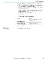
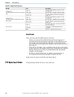
Follow this troubleshooting procedure to diagnose field faults.
Содержание Allen-Bradley 1715-AENTR
Страница 10: ...10 Rockwell Automation Publication 1715 UM001J EN P December 2020 ...
Страница 114: ...114 Rockwell Automation Publication 1715 UM001J EN P December 2020 Chapter 2 Installation Instructions Notes ...
Страница 134: ...134 Rockwell Automation Publication 1715 UM001J EN P December 2020 Chapter 4 Digital I O Operation Notes ...
Страница 200: ...200 Rockwell Automation Publication 1715 UM001J EN P December 2020 Chapter 6 Configure the Redundant I O System Notes ...
Страница 244: ...244 Rockwell Automation Publication 1715 UM001J EN P December 2020 Chapter 9 Redundant I O System Diagnostics Notes ...
Страница 272: ...272 Rockwell Automation Publication 1715 UM001J EN P December 2020 Appendix C Reconfigure a Module Online Notes ...
Страница 290: ...290 Rockwell Automation Publication 1715 UM001J EN P December 2020 Appendix G History of Changes Notes ...
Страница 296: ...296 Rockwell Automation Publication 1715 UM001J EN P December 2020 ...
Страница 297: ...Rockwell Automation Publication 1715 UM001J EN P December 2020 297 Redundant I O System User Manual ...


