126
Rockwell Automation Publication 1715-UM001J-EN-P - December 2020
Chapter 4 Digital I/O Operation
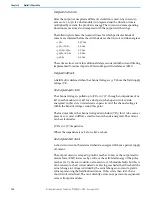
Energized short circuit
After the output is energized a different calculation is used. Any current in
excess of 2.5 A (5 A if a dual module) is integrated and the duration time is
multiplied by current; the product is energy. The current and corresponding
duration are measured and compared with the output switch ratings.
The following list shows the nominal times for which particular bands of
current are tolerated before the switch declares short circuit and de-energizes:
• <5 A:
25.7 ms
• ≥5 A, <10 A:
3.2 ms
• ≥10 A, <15 A:
1.7 ms
• ≥15 A, <20 A:
1.0 ms
• ≥20 A:
0.9 ms
These times also account for additional delays associated with current filtering
implemented to reduce impact of Electro-Magnetic Interference (EMI).
Energized field fault
A field fault is declared when the channel voltage is ≥1 V above the field supply
voltage (VF).
De-energized open circuit
The channel voltage is pulled up to (VF/2)-0.75 V, through an impedance of 26
kΩ in each module (so 13 kΩ for a dual pair) when open circuit and de-
energized. In this state it is declared as open circuit if the channel voltage is
within the band of voltage around this point.
The load must draw the channel voltage down below (VF/3) for it to be seen as
present, so it must still flow a small current when de-energized. The current
can be calculated as:
((VF/6)-0.75 V)/impedance
Where the impedance is 26 kΩ or 13 kΩ as above.
De-energized short circuit
A short circuit cannot be detected when de-energized without a partial supply
of current.
The output current is ramped up until it reaches 50 mA, or the output electro
motive force (EMF) increases by 2 volts, or the calculated energy of the pulse
reaches 5 mJ (a timeout condition also exists to catch module faults but this is
of no concern to short circuit detection). Having reached either threshold, the
actual change in voltage is divided by the actual change in current to yield a
value representing the field load resistance. If this is less than 10 Ω then a
short circuit is declared. The test currently occurs once per minute sequenced
across all output modules.
Содержание Allen-Bradley 1715-AENTR
Страница 10: ...10 Rockwell Automation Publication 1715 UM001J EN P December 2020 ...
Страница 114: ...114 Rockwell Automation Publication 1715 UM001J EN P December 2020 Chapter 2 Installation Instructions Notes ...
Страница 134: ...134 Rockwell Automation Publication 1715 UM001J EN P December 2020 Chapter 4 Digital I O Operation Notes ...
Страница 200: ...200 Rockwell Automation Publication 1715 UM001J EN P December 2020 Chapter 6 Configure the Redundant I O System Notes ...
Страница 244: ...244 Rockwell Automation Publication 1715 UM001J EN P December 2020 Chapter 9 Redundant I O System Diagnostics Notes ...
Страница 272: ...272 Rockwell Automation Publication 1715 UM001J EN P December 2020 Appendix C Reconfigure a Module Online Notes ...
Страница 290: ...290 Rockwell Automation Publication 1715 UM001J EN P December 2020 Appendix G History of Changes Notes ...
Страница 296: ...296 Rockwell Automation Publication 1715 UM001J EN P December 2020 ...
Страница 297: ...Rockwell Automation Publication 1715 UM001J EN P December 2020 297 Redundant I O System User Manual ...


