background image

Rockwell Automation Publication 1715-UM001J-EN-P - December 2020

27

Chapter 1          Redundancy System Overview

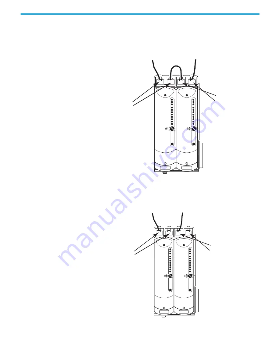
For a DLR (Ring) Topology, the Ethernet ports of the adapters are configured 
with the outward-facing ports (Port 1 of Module A and Port 2 of Module B) 
operating as a 2-port switch. Port 2 of Module A and Port 1 of Module B are 
chained together.

Figure 10 - DLR (Ring) Ethernet Topology

For a STAR Topology, the Ethernet ports of the adapters are configured with 
the leftmost ports (Port 1 of Module A and Port 1of Module B) operating as a 
2-port switch. The rightmost ports on each adapter are left unused.

Figure 11 - STAR Ethernet Topology

Module Status

Redundancy Status

Network Status

Rack Status

Ethernet 1
Ethernet 2

Reset

Ethernet 1
Ethernet 2

Reset

Module A
Port 1
Port 2

Module B
Port 1
Port 2

Module Status

Redundancy Status

Network Status

Rack Status

Ethernet 1
Ethernet 2

Reset

Ethernet 1
Ethernet 2

Reset

Module A
Port 1
Port 2

Module B
Port 1
Port 2

Module Status

Redundancy Status

Network Status

Rack Status

Module Status

Redundancy Status

Network Status

Rack Status

45240

Содержание Allen-Bradley 1715-AENTR

Страница 1: ...Redundant I O System Catalog Numbers 1715 AENTR 1715 IB16D 1715 OB8DE 1715 IF16 1715 OF8I User Manual Original Instructions ...

Страница 2: ...ation Inc with respect to use of information circuits equipment or software described in this manual Reproduction of the contents of this manual in whole or in part without written permission of Rockwell Automation Inc is prohibited Throughout this manual when necessary we use notes to make you aware of safety considerations Labels may also be on or inside the equipment to provide specific precaut...

Страница 3: ...oning in the 1715 Redundant I O System 15 Layout the Hardware 17 System Context 18 Simplex Architecture 20 Duplex Architecture 21 Mixed Architecture 23 Bus Diagram 24 Switchover Considerations 25 Obtaining a New IP Address 26 Ethernet Topology 26 Communication on the EtherNet IP Network 28 System Performance 28 Input Output Traffic Prioritization 28 Connections 28 RPI 29 Connection and Data Format...

Страница 4: ...sure DIN Rail Assembly 56 Step 2 Build the System 56 Product Dimensions 56 DIN Rail Mounting Dimensions 56 DIN Rail Assembly 57 Component Size and Weights 58 Install the Power Supply 60 Install the Adapter Base Unit 61 Install the I O Base Unit 62 Install Termination Assembly to I O Base Unit 64 Mount Termination Assemblies 65 Mount I O Expansion Cable 67 Cable Assembly 67 Expansion Cable 68 Insta...

Страница 5: ... Output Module Compatibility 120 Termination Assemblies 120 Using Features Common to 1715 Standard Digital I O Modules 120 Removal and Insertion Under Power RIUP 120 Module Fault Reporting 121 Fully Software Configurable 121 Module Inhibiting 121 Status Indicator Information 122 Features Specific to 1715 IB16D Digital Input Modules 122 Data Transfer on Either Cyclic Time or Change of State 122 Set...

Страница 6: ... Precautions for HART in a Safety System 142 Configure HART for Field Device Monitoring 142 AB 1715_ChCHART_Struc 144 HART Pass Through 145 Using HART Pass Through 145 HART Pass Through Features 146 Precautions for HART Pass Through in a Safety System 147 Installing the 1715 DTM 147 Updating the Asset Management System DTM Catalogue 149 Enable HART Pass Through in the Controller 150 Using Factory ...

Страница 7: ...mplex Mode 192 1715 OF8I Analog Output Module 193 Add the Analog Output Module to the project 193 Step 1 Add the Analog Output Module in Duplex Mode 193 Step 2 Add the Analog Output Module in Simplex Mode 198 Chapter 7 1715 Redundant I O System in SIL 2 Safety Applications SIL 2 Safety Application Requirements 201 1715 I O Modules in SIL 2 Safety Applications 202 Typical Configurations 203 Interna...

Страница 8: ...odule Add On Instruction 233 Add On Instruction Scan Times 235 Safety Reaction Time Calculations 236 Using the Add On Instruction Data Tags in an Application Program 237 Performing a SIL 2 Reset 238 Chapter 9 Redundant I O System Diagnostics Diagnostic Features 241 Appendix A Status Indicators Faults 245 System Faults 245 Module Faults 245 Channel Faults 246 Field Faults 246 User Application Fault...

Страница 9: ...r Logic 270 Appendix D PFD and PFH Calculations for a SIL 2 System About PFD and PFH Calculations 273 Determine Which Values to Use 273 Calculations for 1715 I O Modules 273 PFD Calculations with 24 hour MTTR 274 Communications Data 276 Appendix E SIL 2 Applications Checklist 1715 I O Modules 277 Appendix F I O Tag Definitions 1715 AENTR Adapter 279 1715 IB16D 280 1715 OB8DE 282 1715 IF16 284 1715...

Страница 10: ...10 Rockwell Automation Publication 1715 UM001J EN P December 2020 ...

Страница 11: ...L 2 applications using revision 2 x of 1715 can use version 19 RSLogix 5000 requires Microsoft Windows Vista Microsoft Windows 7 32 and 64 bit and Microsoft Windows 2003 Server operating systems Studio 5000 environment version 21 or later Studio 5000 requires Microsoft Windows Vista Microsoft Windows 7 32 and 64 bit and Microsoft Windows 2003 Server operating systems ControlFLASH software version ...

Страница 12: ...l publication 1756 UM058 Describes how to install configure and troubleshoot ControlLogix digital I O modules ControlLogix Analog I O Modules User Manual publication 1756 UM009 Describes how to install configure and troubleshoot ControlLogix analog I O modules Using ControlLogix in SIL 2 Applications Safety Reference Manual publication 1756 RM001 Describes the guidelines for using ControlLogix con...

Страница 13: ...connected directly to the adapter base unit and other I O base units or through expansion cables The 1715 Redundant I O System is a modular system in which the adapter and I O base units snap together by using mating connectors and retaining clips to form the backplane One module in a duplex pair can be removed and replaced without system interruption The base units via termination assemblies prov...

Страница 14: ...e The use of termination assemblies communicates the I O mode of operation you choose Simplex or Duplex to your system through the backplane the adapter and I O base units Termination Assemblies The termination assembly TA matches your software configuration for simplex or duplex Attached to an I O base the TA can start in any slot and can span multiple connected bases When modules are used in Dup...

Страница 15: ...25 The first two positions always contain the redundant adapter pair in slots 0 and 1 The remaining positions begin numbering at slot 2 and contain the I O modules ending at slot position number 25 Any combination of simplex or duplex I O module pairs can be used in the I O base units See Table 2 for a sample of what a system could look like Expansion cables can be used to connect base units as sh...

Страница 16: ...apter B 2 I O 01 First I O base unit Module A of first duplex pair 3 I O 02 Module B of first duplex pair 4 I O 03 Module A of second duplex pair 5 I O 04 Second I O base unit Module B of second duplex pair 6 I O 05 First simplex module 7 I O 06 Module A of third duplex pair 8 I O 07 Third I O base unit Module B of third duplex pair 9 I O 08 Second simplex module 10 I O 09 Third simplex module 11 ...

Страница 17: ...l Module Status Redundancy Status Network Status Rack Status Ethernet 1 Ethernet 2 Reset Healthy Ready Run Healthy Ready Run Healthy Ready Run Healthy Ready Run Healthy Ready Run Healthy Ready Run Healthy Ready Run Healthy Ready Run Healthy Ready Run Healthy Ready Run Healthy Ready Run Healthy Ready Run Healthy Ready Run Healthy Ready Run Healthy Ready Run Healthy Ready Run Healthy Ready Run Healt...

Страница 18: ...re 2 1715 Redundant I O System DLR Ring Topology Attached to a 1756 ControlLogix Enhanced Redundancy System 1756 RM2 1756 EN2TR IO BASE 1715 A310 CH1 CH1 CH1 CH1 CH1 CH1 CH1 CH1 TERMINAL IDENTITY AOTA Dual CH1 CH1 CH1 CH1 CH1 CH1 CH1 CH1 TERMINAL IDENTITY AOTA Dual CH1 CH1 CH1 CH1 CH1 CH1 CH1 CH1 TERMINAL IDENTITY AOTA Dual IO BASE 1715 A310 CH1 CH1 CH1 CH1 CH1 CH1 CH1 CH1 TERMINAL IDENTITY AOTA D...

Страница 19: ...756 RM2 1756 EN2T IO BASE 1715 A310 CH1 CH1 CH1 CH1 CH1 CH1 CH1 CH1 TERMINAL IDENTITY AOTA Dual CH1 CH1 CH1 CH1 CH1 CH1 CH1 CH1 TERMINAL IDENTITY AOTA Dual CH1 CH1 CH1 CH1 CH1 CH1 CH1 CH1 TERMINAL IDENTITY AOTA Dual IO BASE 1715 A310 CH1 CH1 CH1 CH1 CH1 CH1 CH1 CH1 TERMINAL IDENTITY AOTA Dual CH1 CH1 CH1 CH1 CH1 CH1 CH1 CH1 TERMINAL IDENTITY AOTA Dual CH1 CH1 CH1 CH1 CH1 CH1 CH1 CH1 TERMINAL IDENT...

Страница 20: ...n in The CIP Networks Library Volume 2 Edition 1 21 section 8 9 4 3 ODVA Inc 2016 For more information regarding ODVA visit www odva org Simplex Architecture Simplex I O modules fail safe on the first detected module fault The process under control shuts down when the fault is detected This configuration is suitable for high and low demand module applications Resistor RJ 45 Shield Transient Protec...

Страница 21: ...he duplex arrangement can be used for low demand and high demand applications IO BASE 1715 A310 CH1 CH1 CH1 CH1 CH1 CH1 CH1 CH1 TERMINAL IDENTITY AOTA Dual CH1 CH1 CH1 CH1 CH1 CH1 CH1 CH1 TERMINAL IDENTITY AOTA Dual CH1 CH1 CH1 CH1 CH1 CH1 CH1 CH1 TERMINAL IDENTITY AOTA Dual 1715 AENTR 1715 AENTR 1715 IB16D 1715 OB8DE ADAPTER ADAPTER O P I P SENSORS FINAL ELEMENTS 1715 TADOB8DE 1715 TADIB16D 1715 ...

Страница 22: ...2 Rockwell Automation Publication 1715 UM001J EN P December 2020 Chapter 1 Redundancy System Overview Figure 6 Duplex Architecture Duplex Inputs Simplex Output ADAPTER ADAPTER O P I P I P CLX CIP NETWORK ...

Страница 23: ... AENTR ADAPTER ADAPTER O P I P SENSORS FINAL ELEMENTS IO BASE 1715 A310 CH1 CH1 CH1 CH1 CH1 CH1 CH1 CH1 TERMINAL IDENTITY AOTA Dual CH1 CH1 CH1 CH1 CH1 CH1 CH1 CH1 TERMINAL IDENTITY AOTA Dual CH1 CH1 CH1 CH1 CH1 CH1 CH1 CH1 TERMINAL IDENTITY AOTA Dual 1715 IB16D 1715 IF16 I P O P IO BASE 1715 A310 CH1 CH1 CH1 CH1 CH1 CH1 CH1 CH1 TERMINAL IDENTITY AOTA Dual CH1 CH1 CH1 CH1 CH1 CH1 CH1 CH1 TERMINAL ...

Страница 24: ...ual CH1 CH1 CH1 CH1 CH1 CH1 CH1 CH1 TERMINAL IDENTITY AOTA Dual CH1 CH1 CH1 CH1 CH1 CH1 CH1 CH1 TERMINAL IDENTITY AOTA Dual 1715 IB16D 1715 OB8DE I P O P IO BASE 1715 A310 CH1 CH1 CH1 CH1 CH1 CH1 CH1 CH1 TERMINAL IDENTITY AOTA Dual CH1 CH1 CH1 CH1 CH1 CH1 CH1 CH1 TERMINAL IDENTITY AOTA Dual CH1 CH1 CH1 CH1 CH1 CH1 CH1 CH1 TERMINAL IDENTITY AOTA Dual 1715 IB16D 1715 OB8DE 1715 TADOB8DE 1715 TADIB16...

Страница 25: ...apters are present because it uses the primary IP address and because it is the module responsible for receiving transmitting to ControlLogix controller on the EtherNet IP network The module in the rightmost slot is considered the secondary module partner and uses the primary IP address 1 For example if the primary module in the leftmost slot has an IP address of N then the secondary module in the...

Страница 26: ...n If the B module becomes the primary module because you must replace the A module that is not enough cause to swap IP addresses back again Module B remains as the primary module Obtaining a New IP Address The IP address of the primary module is stored in the adapter base unit through interaction with the TCP IP object If a stored primary IP address is available the adapter uses that address If a ...

Страница 27: ...e configured with the leftmost ports Port 1 of Module A and Port 1of Module B operating as a 2 port switch The rightmost ports on each adapter are left unused Figure 11 STAR Ethernet Topology Module Status Redundancy Status Network Status Rack Status Ethernet 1 Ethernet 2 Reset Ethernet 1 Ethernet 2 Reset Module A Port 1 Port 2 Module B Port 1 Port 2 Module Status Redundancy Status Network Status ...

Страница 28: ...to communicate to an I O module of a type that is not the same as the physically installed module The termination assembly type simplex duplex determines the CIP messages for corresponding CIP objects that the adapter processes for each I O module System Performance This section discusses connections and RPI settings for the 1715 Redundant I O System Input Output Traffic Prioritization Note In ord...

Страница 29: ...50 ms Connection and Data Format The adapter and I O modules each support one data connection for input output data Listen Only connections are not supported Table 3 RSLogix 5000 or Studio 5000 Logix Designer Configuration Connection Module Duplex Simplex Module Description 1 1715 AENTR Duplex Ethernet Adapter 1 1715 IB16D Duplex 16 point Digital Input 1 1715 OB8DE Duplex 8 point Diagnostic Digita...

Страница 30: ...001J EN P December 2020 Chapter 1 Redundancy System Overview Timestamping A timestamp is the time an event occurred It is recorded by the 1715 system and passed to ControlLogix Timestamp resolution is in μs but 1715 is accurate to 10 ms typical ...

Страница 31: ...les to allow for additional space requirements for the system within an enclosure Topic Page Before You Begin 36 System Hardware Components 38 System Software 51 Module Placement 53 Install Summary 55 Product Dimensions 56 DIN Rail Assembly 57 Install the Power Supply 60 Install the Adapter Base Unit 61 Install the I O Base Unit 62 Install Termination Assembly to I O Base Unit 64 Mount I O Expansi...

Страница 32: ...e type ratings that are required to comply with certain product safety certifications In addition to this publication see the following Industrial Automation Wiring and Grounding Guidelines publication 1770 4 1 for additional installation requirements NEMA Standard 250 and IEC 60529 as applicable for explanations of the degrees of protection provided by enclosures ATTENTION This equipment is sensi...

Страница 33: ... Enclosure is to be marked with the following Warning Do not open when energized After installation of subject devices into the enclosure access to termination compartments shall be dimensioned so that conductors can be readily connected Grounding conductor should have a minimum cross sectional area of 3 31 mm 12 AWG Subject devices are for use in an area of not more than pollution degree 2 in acc...

Страница 34: ...ore proceeding WARNING If you connect or disconnect wiring while the field wire power is on an electrical arc can occur This could cause an explosion in hazardous location installations Be sure that power is removed or the area is nonhazardous before proceeding WARNING If you insert or remove a base unit or termination assembly while power is applied an electrical arc can occur This could cause an...

Страница 35: ...e de température le plus défavorable code de température le plus faible peut être utilisé pour déterminer le code de température global du système Les combinaisons d équipements dans le système sont sujettes à inspection par les autorités locales qualifiées au moment de l installation EXPLOSION HAZARD Do not disconnect equipment unless power has been removed or the area is known to be nonhazardous...

Страница 36: ...void and the equipment will not be covered IMPORTANT Throughout this manual some graphics do not depict the actual hardware as required These graphics are for representational purposes only and do not necessarily reflect the actual component layout of your system Table 4 Parts Table Cat No Description 1715 AENTR Adapter 1715 IB16D 16 channel digital input module 1715 OB8DE 8 channel digital output...

Страница 37: ...Channel07 Channel 08 Channel 01 Channel 02 Channel 03 Channel 04 Channel 05 Channel 06 Channel07 Channel 08 Channel 09 Channel 10 Channel 11 Channel 12 Channel 13 Channel 14 Channel15 Channel 16 Channel 01 Channel 02 Channel 03 Channel 04 Channel 05 Channel 06 Channel07 Channel 08 Channel 09 Channel 10 Channel 11 Channel 12 Channel 13 Channel 14 Channel15 Channel 16 Module Status Redundancy Status...

Страница 38: ...ll 1715 modules IO BASE 1715 A310 CH1 CH1 CH1 CH1 CH1 CH1 CH1 CH1 TERMINAL IDENTITY AOTA Dual CH1 CH1 CH1 CH1 CH1 CH1 CH1 CH1 TERMINAL IDENTITY AOTA Dual CH1 CH1 CH1 CH1 CH1 CH1 CH1 CH1 TERMINAL IDENTITY AOTA Dual Ethernet 1 Ethernet 2 Reset Ethernet 1 Ethernet 2 Reset Channel 00 Channel 01 Channel 02 Channel 03 Channel 04 Channel 05 Channel 06 Channel 07 Channel 08 Channel 09 Channel 10 Channel 1...

Страница 39: ...dule 1715 OF8I 8 channel analog output module 32096 M Rack Status Ethernet 1 Ethernet 2 1715 AENTR ADAPTER Reset Module Status Redundancy Status Network Status 32096 M Rack Status Ethernet 1 Ethernet 2 1715 AENTR ADAPTER Reset Module Status Redundancy Status Network Status Rack Status Ethernet 1 Ethernet 2 1715 AENTR ADAPTER Reset Module Status Redundancy Status Network Status 32096 M Do not open ...

Страница 40: ... 01 Channel 02 Channel 03 Channel 04 Channel 05 Channel 06 Channel 07 1715 OB8DE DIGITAL OUTPUT Healthy Ready Run Channel 00 Channel 01 Channel 02 Channel 03 Channel 04 Channel 05 Channel 06 Channel 07 1715 IF16 ANALOG INPUT Channel 08 Channel 09 Channel 10 Channel 11 Channel 12 Channel 13 Channel 14 Channel 15 Healthy Ready Run Channel 00 Channel 01 Channel 02 Channel 03 Channel 04 Channel 05 Cha...

Страница 41: ...s The 1715 A2A adapter base unit contains four fuses To replace the fuses follow this procedure 1 Lift the door to access the fuses The fuses are labeled from F1 F4 from left to right The replacement fuse part number is Littelfuse 0154004 DRT 2 With a pair of small long nosed pliers remove and replace the blown fuse 32060 M ...

Страница 42: ...ses Fuses F1 and F3 have independent tags under the 1715 AENTR module status flags For example in Figure 17 F3 is blown or adapter power is missing to the PWR 2 connector 32060 M Lift door to access fuses Use replacement fuse 4 A slow blow fuses in OMNI BLOK holders manufactured by Littelfuse Remove and replace with a pair of long nosed pliers Fuses ...

Страница 43: ...id red indicates a blown F2 or F4 fuse The adapter tags indicate each individual I O module tag ModAFault and ModBFault as shown in Figure 18 Figure 18 Adapter Tags Indicate Faults 1715 A3IO I O Base Unit The I O base unit holds up to three I O modules IMPORTANT After any fuse replacement or power related issue on PWR 1 PWR 2 the Reset button on the 1715 AENTR must be pressed to clear the fault an...

Страница 44: ...termination assemblies two for each module depending on the architecture of your system and the I O modules you are going to use 32059 M Table 5 I O Termination Assembly Descriptions I O Module Termination Assembly Cat No Termination Assembly Description 1715 IB16D 1715 TASIB16D Digital input simplex 1715 TADIB16D Digital input duplex 1715 OB8DE 1715 TAS0B8DE Digital output simplex 1715 TADOB8DE D...

Страница 45: ...age input protection There are two types of digital input termination assemblies A 1715 TASIB16D 16 channel simplex TA that provides termination for 16 digital input channels and mates with one 1715 IB16D digital input module A 1715 TADIB16D 16 channel duplex TA that provides termination for 16 digital input channels and mates with up to two 1715 IB16D digital input modules 1715 IF16 1715 TASIF16 ...

Страница 46: ...at provides fault tolerant operation for 8 digital output channels and mates with redundant 1715 OB8DE digital output modules 32120 M Fuse Fuse Holder Channel Channel TB1 TB2 CH0 CH1 CH2CH3 CH4CH5 CH6CH7 CH8CH9 CH10CH11CH12CH13CH14CH15 FS1 FS3 FS5 FS7 FS2 J1 16 c c c c 1 1 1 1 16 16 16 J2 J4 J3 FS4 FS6 FS8 FS9 FS11 FS13 FS15 FS10 FS12 FS14 FS16 16 16 16 16 FH1 FH1 FH2 FH2 FH3 FH3 FH4 FH4 FH5 FH5 F...

Страница 47: ...gle ended analog input channels and mates with one 1715 IF16 16 channel analog input module There is no channel isolation A 1715 TADIF16 16 channel duplex TA that provides termination for 16 isolated analog input channels and mates with up to two 1715 IF16 16 channel analog input modules The channels are isolated 32121 M TB1 TB2 TB3 TB4 J1 J2 c c Ov CH0CH1 CH2CH3 CH4CH5 CH6CH7 V1 Ov V1 Ov V2 Ov V2...

Страница 48: ...I 8 channel analog output module A 1715 TADOF8 8 channel duplex termination assembly provides fault tolerant operation for 8 analog output channels through inter module communication and by routing the output source current from two modules to the same field device CH0 CH1 CH2 CH3 CH4 CH5 CH6 CH7 CH8 CH9 CH10 CH11 CH12 CH13 CH14 CH15 32120 M Fuse Fuse Holder Channel Channel TB1 TB2 CH0 CH1 CH2CH3 ...

Страница 49: ... the channel outputs from two 8 channel analog output modules in parallel to 8 field devices Therefore each field device receives a current source from a channel on each of two modules So if one module fails or one or more channels fail on a module the outputs from the second module continues to supply the field devices J1 J2 c c CH0 1 2 3 4 5 6 7 CH LOOP DAOTA PCB130861 REV A LOOP TB1 J1 J2 J4 J3...

Страница 50: ...le Power Requirements A 24V DC power supplied is required See Install the Power Supply on page 60 for complete details 32086 M CH1 CH1 CH1 CH1 CH1 CH1 CH1 CH1 TERMINAL IDENTITY AOTA Dual Ethernet 1 Ethernet 2 Reset Ethernet 1 Ethernet 2 Reset Rack Status Module Status Redundancy Status Network Status Rack Status Module Status Redundancy Status Network Status Slot Filler Covers 32078 M ATTENTION To...

Страница 51: ...uirements If enclosure is in colder environments temperatures must be kept at 20 C 4 F or above Specify an Enclosure An enclosure for the 1715 Redundant I O System must be designed for the specific environmental conditions that are present It must support the weight of the system provide mechanical protection and remove the heat that the system creates If the application of the adapter is not usin...

Страница 52: ... firmware from 1715 revision 3 001 or later is installed and running Recovery mode firmware revision 1 011 or later Dual 1715 AENTR modules are updated at the same time Each I O module is updated separately even if it is fitted to a dual termination assembly Update procedure Run the ControlFLASH program Select the type of module from the list Browse to the 1715 AENTR and open it open the Backplane...

Страница 53: ...OTA Dual CH1 CH1 CH1 CH1 CH1 CH1 CH1 CH1 TERMINAL IDENTITY AOTA Dual CH1 CH1 CH1 CH1 CH1 CH1 CH1 CH1 TERMINAL IDENTITY AOTA Dual Ethernet 1 Ethernet 2 Reset Ethernet 1 Ethernet 2 Reset Channel 00 Channel 01 Channel 02 Channel 03 Channel 04 Channel 05 Channel 06 Channel 07 Channel 08 Channel 09 Channel 10 Channel 11 Channel 12 Channel 13 Channel 14 Channel 15 IO BASE 1715 A310 CH1 CH1 CH1 CH1 CH1 C...

Страница 54: ...occupy the slots of the adapter base An adapter base unit can support up to 8 I O base units up to 24 I O modules on its right side Module positions within the I O base units are numbered from 2 25 the leftmost position being slot 2 The total number of slot positions in the system is 26 adapters occupy slots 0 1 and I O modules occupy slots 2 25 Expansion cables can be used to connect base units a...

Страница 55: ...H1 CH1 CH1 CH1 CH1 CH1 TERMINAL IDENTITY AOTA Dual CH1 CH1 CH1 CH1 CH1 CH1 CH1 CH1 TERMINAL IDENTITY AOTA Dual Module Status Redundancy Status Network Status Rack Status Ethernet 1 Ethernet 2 Reset Healthy Ready Run Healthy Ready Run Healthy Ready Run Healthy Ready Run Healthy Ready Run Healthy Ready Run Healthy Ready Run Healthy Ready Run Healthy Ready Run Healthy Ready Run Healthy Ready Run Heal...

Страница 56: ...ct adapter and I O base units 5 Install anchor end stops onto the DIN rails 6 Mount termination assemblies to the base units 7 Mount I O expansion cable if needed 8 Wire the adapter base Connect to power Wire the ground Connect to field wiring 9 Connect the adapter to the Ethernet network 10 Module keying verify coding peg positions 11 Install the adapter redundant module pair 12 Install the I O m...

Страница 57: ...L IDENTITY AOTA Dual Module Status Redundancy Status Network Status Rack Status Ethernet 1 Ethernet 2 Reset Ethernet 1 Ethernet 2 Reset Channel 00 Channel 01 Channel 02 Channel 03 Channel 04 Channel 05 Channel 06 Channel 07 Channel 08 Channel 09 Channel 10 Channel 11 Channel 12 Channel 13 Channel 14 Channel 15 IO BASE 1715 A310 CH1 CH1 CH1 CH1 CH1 CH1 CH1 CH1 TERMINAL IDENTITY AOTA Dual CH1 CH1 CH...

Страница 58: ...e unit and module is 136 mm 5 375 in Figure 24 Module Dimensions All module dimensions are the same whether they are adapters or I O modules Table 6 Component Sizes Item Size H x W x D Adapter base unit 224 x 84 x 30 mm 8 82 x 3 31 x 1 18 in I O module base unit 233 x 126 x 18 mm 9 25 x 5 x 0 75 in Module 166 x 42 x 118 mm 6 5 x 1 625 x 4 625 in 32067 M ...

Страница 59: ...mber 2020 59 Chapter 2 Installation Instructions Figure 25 System Dimensions Be sure that the mounting assembly can support the weight of the components by using this table 84 mm 3 31 in 126 mm 4 96 in 233 mm 9 17 in 237 mm 9 33 in 237 mm 9 33 in 32068 M ...

Страница 60: ...7 1715 TASOB8DE Digital output simplex termination assembly 133 4 69 1715 TADOB8DE Digital output duplex termination assembly 260 9 17 1715 TASOF8I Analog output simplex termination assembly 133 4 69 1715 TADOF8I Analog output duplex termination assembly 260 9 17 1715 N2S Short blank slot filler 40 1 41 1715 N2T Tall blank slot filler 50 1 76 Power supply User supplied Varies 1 All weights are app...

Страница 61: ...ts and two adapters on the front of the unit and one I O base connector on the right hand side of the unit The connections for the adapters are commonly referred to as adapter slots To mount the 1715 A2A adapter base unit follow these steps 1 Place the 1715 A2A adapter base unit onto the DIN rails and position them toward the left leaving space for the I O base units to the right 2 Secure the adap...

Страница 62: ...e right hand side and on the front connections for three I O termination assemblies and three I O modules The locations for each I O termination assembly and I O module connectors are paired and together represent an I O module slot To mount the 1715 A3IO base unit follow these steps 1 Mount each 1715 A3IO base unit onto the DIN rails to the right of the 1715 A2A adapter base unit 2 Slide the base...

Страница 63: ...the bottom retaining lever below the base unit as far to the left as it goes until it latches in the locked position 4 Insert the retaining clips into the top and the bottom slots to connect the adapter base unit to the I O base unit Adapter Base Unit I O Base Unit Retaining Clip Retaining Clip DIN Rails Retaining Lever Mating Connector Retaining Lever 45247 ...

Страница 64: ...he back of one or more installed I O modules I O termination assemblies are available in single width and double width varieties A single width I O termination assembly connects the field wiring to one I O module slot for simplex operation where a double width I O termination assembly connects the field wiring to two I O module slots for duplex redundant operation I O termination assemblies can sp...

Страница 65: ...ion and removal of modules does not disturb other electrical connections Mount Termination Assemblies Termination assemblies connect to I O base units A combination of duplex and simplex Termination Assemblies may be mounted A duplex Termination Assembly may be mounted across two I O base units The combination that is used depends on the specific configuration requirements of the system To connect...

Страница 66: ...66 Rockwell Automation Publication 1715 UM001J EN P December 2020 Chapter 2 Installation Instructions 3 Make sure the retaining tab clips over the circuit board to secure the TA in position 32061 M ...

Страница 67: ...to 24 I O modules The maximum length of an entire bus or backplane the combination of I O base units and expansion cables is 10 m The assembly consists of a cable terminated by multi way plugs and a pair of adapters The expansion cable offers these features Two meter cable length Secure with retaining screws and screw cap screws Connects all command and response signals and system power Screened t...

Страница 68: ...xpansion cable has a left cable adapter and a right cable adapter Connect one end to the right hand bus connector of an I O base or adapter base unit The other end connects to the left hand bus connector of an I O base unit Figure 27 I O Expansion Cable Adapters 32080 M Item Description 1 SCSI 3 cable 2 Ferrite 3 Cable tie Cable Adapter 32086 M Cable Adapter Item Description 1 Cable socket assembl...

Страница 69: ...nnect to a 1715 A3IO 3 slot I O Base Unit 1 To extend from the right hand side of an I O base unit insert a cable plug assembly into the I O backplane connector Terminators are not required at the end of the bus last base unit 32081 M Table 9 Expansion Cable Components Item Description 1 M3 socket cap screw 2 Cable plug assembly 3 Cable socket assembly 4 M3 nut IMPORTANT Adapter base units can onl...

Страница 70: ...2020 Chapter 2 Installation Instructions 2 When installing the cable on the left side of the base unit insert a cable socket assembly into the I O backplane connector 3 Insert an M3 nut into the base unit molding assembly as shown 32081 M 32081 M 32081 M 32081 M ...

Страница 71: ...ther end of the cable into the cable plug or socket assembly Connect to a 1715 A2A 2 slot Adapter Base Unit 1 When installing the expansion cable from the right hand side insert a cable plug assembly into the 1715 A2A adapter base unit connector 2 Follow steps 3 4 and 5 3 Insert the cable end into the cable plug assembly and tighten the retaining screws by hand 4 Fit the cable socket assembly to t...

Страница 72: ...urces with a common return Power is connected to the two plugs PWR 1 and PWR 2 on the adapter base plate Power is distributed to the I O modules through the base units Figure 28 Connect System Power 32060 M Connect cable plug assembly to the adapter base connector Adapter Base Connector Pwr1 Pwr2 24V DC 24V DC C o m m o n C o m m o n 32065 M1 ATTENTION To comply with the CE Low Voltage Directive L...

Страница 73: ...n The system can have up to three separate ground systems An AC Safety Ground sometimes called the dirty ground to help protect you in the event of a fault The ground stud on the adapter base unit must be connected to the AC safety ground along with all exposed metalwork such as DIN rails An Instrument Ground sometimes called the clean ground or OV DC ground to provide a good stable OV reverence f...

Страница 74: ...nect the field wiring to the screw terminal blocks on the termination assemblies MP PWR 24V1 OV MP PWR 24V2 OV 32125 M AC Ground Connection Only IMPORTANT The termination assemblies have integral fuses IMPORTANT You must use safety wiring principles if the applicable standards for the system require you take precautions to avoid external short circuits because the internal diagnostics in the 1715 ...

Страница 75: ... Chapter 2 Installation Instructions Recommended Circuits for Digital Inputs These circuits can be used for simplex and duplex configurations of digital input modules Fit a fuse in each circuit to help protect the field wiring Figure 31 Standard Input DC 5 11 33113 M ...

Страница 76: ...32 Line Monitored Inputs Threshold Settings for Line Monitored Field Devices For information about setting threshold values see Threshold Values for Digital Inputs on page 299 It is recommended that you do a manual calibration drift check every two years See Calibration Drift Checks on page 311 DC 5 11 32114 M ...

Страница 77: ... undervoltage detection circuits Supply voltage monitoring initiates a warning signal and Power off Protection mode when a power failure is detected Internal diagnostics test the module every application cycle to see whether values are within the 1 value fault band and if appropriate report a fault An independent watchdog arrangement also monitors the module operation and provides more fault conta...

Страница 78: ...les Field Wiring of Digital Input Termination Assemblies The termination assembly routes each digital input through a circuit See Figure 34 The input channel is protected with a 50 mA fuse When an extreme over voltage is applied to the input the fuse blows Each digital input signal is terminated by 5 11 k high reliability load and is fed to the input circuit of the input module Figure 34 1715 TASI...

Страница 79: ...0V 0V CH1 CH2 CH3 CH4 CH5 CH6 CH7 CH8 CH9 CH10 CH11 CH12 CH13 CH14 CH15 CH16 Fuse Fuse Holder Channel Channel TB1 TB2 CH0 CH1 CH2CH3 CH4CH5 CH6CH7 CH8CH9 CH10CH11CH12CH13CH14CH15 FS1 FS3 FS5 FS7 FS2 J1 16 c c c c 1 1 1 1 16 16 16 J2 J4 J3 FS4 FS6 FS8 FS9 FS11 FS13 FS15 FS10 FS12 FS14 FS16 1715 TASIB16D Digital Input Simplex Termination Assembly 1715 TADIB16D Digital Input Duplex Termination Assemb...

Страница 80: ... is necessary to ensure that the input signal condition satisfies the maximum slew rate criteria that are defined in the 1715 Redundant I O System Specifications Technical Data publication 1715 TD001 So it can be necessary to condition the input signal with low pass filtering Field Loop Circuits for Digital Inputs The recommended digital input field loop circuits for the 1715 IB16D digital input m...

Страница 81: ...pter 2 Installation Instructions the output termination assembly They help protect all output circuits that are associated with the particular termination assembly ATTENTION For inductive loads connect a diode at the actuator to protect the adapter against back EMF 46198 ...

Страница 82: ... the output FET switches accordingly The output voltages are produced from the 24V DC field power input voltages by a power combiner circuit Each output channel has a pair of FET switches arranged in a series that are independently controlled Load current and voltage monitoring is provided for each switch Output channel protection makes sure that the output circuit is switched off when the channel...

Страница 83: ...checked for stuck on and stuck off conditions on the output switch pairs The stuck on stuck off test is performed on one 1715 OB8DE module per minute Field Wiring of Digital Output Termination Assemblies The 1715 TASOB8DE and 1715 TADOB8DE consist of a simple PCB screw termination blocks 16 terminals two 10A fuses with a plastic fuse cover coding pegs field terminal connectors and connectors to co...

Страница 84: ... at the terminal blocks and fed via two replaceable 10 A fuses F1 and F2 These fuses give protection for the output module against field faults Field OV VFIELD RTN is also routed from the output module connectors to the terminal block Figure 41 1715 TASOB8DE Digital Output Simplex Termination Assembly Connections OV OV OV V1 V2 V1 V2 OV To Next TA if fitted TB1 TB2 TB3 TB4 CH0 CH2 CH4 CH6 CH1 CH3 ...

Страница 85: ... that channels can be declared faulted as a consequence of diagnostics that are otherwise designed to verify the channels are operating within their designed safety accuracy VFIELD1 24V DC VFIELD2 24V DC VFIELD RTN OV Fuse F2 Fuse F1 Digital Output Fail Safe Channel Array Connector J1 DO Module Digital Output Fail Safe Channel Array Connector J2 DO Module DO CH0 DO CH1 DO CH2 DO CH3 DO CH4 DO CH5 ...

Страница 86: ...al Output Simplex or Duplex Field Loop Circuit Recommended Circuits for Analog Inputs This section describes the layout for analog inputs IMPORTANT The field power 5A fuses comply with UL508 requirements The 5A fuses are No 396 TE5 5A time lag fuse UL 248 14 125 V T Leadfree manufactured by Littelfuse You can use Class 2 power supplies for the 24V DC field voltage instead of the two 5A fuses The N...

Страница 87: ...tics which the adapter controls test the module at routine intervals of 50 100 ms An independent watchdog arrangement also monitors the module operation and provides more fault containment by activating a shutdown mechanism when a fault is detected Channel 0 Channel 1 Channel 2 Channel 3 Channel 4 Channel 5 Channel 6 Channel 7 Field Inputs Termination Assembly Dual Redundant System Power SYS_24V1 ...

Страница 88: ...des flexible input connectivity by mating specific termination assemblies with the relevant number of input modules Field Loop Circuits for Analog Inputs These circuits can be used for simplex and duplex configurations of analog input modules Fit a suitably rated fuse F1 in each circuit to help protect the field wiring terminal block and 4mA 20mA current generator This field loop connection method...

Страница 89: ...l block and 4mA 20mA current generator Figure 48 Four wire Analog Input Field Wiring of Analog Input Termination Assemblies The termination assembly routes each analog input through a circuit similar to that shown in Figure 49 The input channel is protected with a 50 mA fuse Shield Required Terminal Blocks OV Termination Assembly 24V DC 4 20 mA 3 Wire Analog Input 50 mA 120 Ω 32117 M F2 Shield Req...

Страница 90: ...In duplex configurations they are routed in parallel to two modules Figure 49 Analog Input Termination Assembly Input Circuit When an analog input module is configured as dual the analog field loop that is connected to channel 0 is automatically fed to both modules The system automatically votes the data from the input modules so that you have only one value that is presented to the application Th...

Страница 91: ...e to channel 0 and to channel 1 The two input values 0 and 1 then must be voted by using logic or a function block in the application program This is accomplished by taking either the lowest or highest value depending on the application The other option is to use the two values in two simplex input modules for example both using channel 0 In this case the values must still be voted in the applicat...

Страница 92: ...que of 0 5 N m 0 37 lb ft to the terminal screws HART Secondary Master The HART Secondary Master is a hand held monitor controller used by field engineers to check and reconfigure the settings of field equipment In order that the Rockwell modules interface and operate with this equipment an additional 120 Ω resistor assembly is required in the connecting circuit OV OV CH0 CH1 CH2 CH3 CH4 CH10 CH11...

Страница 93: ... secondary Master and 120 Ω resistor assembly to the 0 V terminal and required channel terminal on the terminal block as shown in Figure 54 below IMPORTANT It is the responsibility of the Installation Engineer to ensure that the HART secondary Master is correctly installed information regarding HART equipment may be obtained from the HART website http en hartcomm org http en hartcomm org hcp tech ...

Страница 94: ...for Analog Output Modules This section describes the wiring for analog outputs 32120 M Fuse Fuse Holder Channel Channel TB1 TB2 CH0 CH1 CH2CH3 CH4CH5 CH6CH7 CH8CH9 CH10CH11CH12CH13CH14CH15 FS1 FS3 FS5 FS7 FS2 J1 16 c c c c 1 1 1 1 16 16 16 J2 J4 J3 FS4 FS6 FS8 FS9 FS11 FS13 FS15 FS10 FS12 FS14 FS16 120 Ω HART Secondary Master Field Connections This Side FH1 FH2 FH7 FH6 FH5 FH4 FH3 FH9 FH8 FH10 FH1...

Страница 95: ...ith the limits set by the compliance operating voltage range of the module Field Loop Circuit for Analog Outputs The field loop circuit for an analog output is shown in Figure 56 CH LOOP DAOTA PCB130861 REV A LOOP TB1 J1 J2 J4 J3 0 1 TB2 2 3 TB3 4 5 TB4 6 7 32122 M 1715 TADOF8 Analog Output Duplex Termination Assembly 1715 TASOF8 Analog Output Simplex Termination Assembly 32123 M Field Connections...

Страница 96: ...gure 57 The figure shows when the field power is used to supply the load Figure 57 Field Power Circuit for Analog Outputs Connect the Adapter to the Ethernet Network The adapter supports DLR Ring and Star topologies For more details on topologies see System Architecture on page 16 System 24V DC OV Termination Assembly Analog Output Module CH CH Load 32109 M Field 24V DC OV Termination Assembly Ana...

Страница 97: ...that the length of the cable does not exceed 100 m 328 ft Module Keying Module keying or polarization prevents the wrong module from being inserted into the wrong base unit Modules are supplied with coding pegs that are already fitted so the modules are already keyed Electronic Keying is used within the Logix Designer application See Electronic Keying on page 100 for more information IMPORTANT The...

Страница 98: ...ith A being on the top Each peg or key is fitted in the base unit so that the index recess is next to the relevant numbered position See Figure 59 which shows a photograph of the Adapter Base Unit Coding peg A is absent Coding Peg Positions 32062 M 32085 M Coding Peg Socket Table 12 Allocations of Coding Pegs Application Key A Key B Key C 1715 Adapter Base Unit Not Available 2 1 1715 Digital Input...

Страница 99: ...ructions Figure 59 Inserted Coding Pegs for Adapter Base Unit Verify Coding Pegs To verify that each coding peg also known as a polarizing pin is positioned correctly follow these steps 1 Review the diagram on the adapter base unit that shows the six possible positions for a coding peg 32062 M ...

Страница 100: ...control system It compares the device that is defined in your project to the installed device If keying fails a fault occurs These attributes are compared The following Electronic Keying options are available Coding Peg 32063 M 32062 M Attribute Description Vendor The device manufacturer Device Type The general type of the product for example digital I O module Product Code The specific type of th...

Страница 101: ...tes that the keying attributes are not considered when attempting to communicate with a device With Disable Keying communication can occur with a device other than the type specified in the project ATTENTION Be extremely cautious when using Disable Keying if used incorrectly this option can lead to personal injury or death property damage or economic loss We strongly recommend that you do not use ...

Страница 102: ...ure by allowing you to order the replacement parts without disturbing the system 3 Check the coding pegs on the 1715 A2A adapter backplane and verify that they match the sockets on the back of the adapter 4 Verify that the slot on the head of the adapter clamp screw is vertical IMPORTANT You must inspect the connector pins before you install the modules If you install modules with bent or damaged ...

Страница 103: ... addresses The MAC addresses are between slot 0 and 1 of the adapter base Every hardware component has its own unique MAC address This hardware address is affixed to the hardware on a label 6 Place the new module on to the dowel pin on the adapter base unit Unlocked Position 32084 M 32077 M 32077 M Connect To Dowel Pins ...

Страница 104: ...ddress to the primary adapter This is done by associating an IP address to the MAC address of the primary hardware component in this case the adapter base unit Assign only one primary IP address to the MAC address Table 13 Start up Sequence 1715 AENTR Adapter Indicator Status Module Status Steady green Redundancy Status Flashes then steady green Network Status Off Rack Status Off then steady green...

Страница 105: ... Address on the BOOTP DHCP Server To assign an address follow this procedure to launch the BOOTP DHCP server 1 From the Start button choose Programs Rockwell Software BOOTP DHCP Server BOOTP DHCP Server 2 Verify BOOTP network settings Choose Tools Network Settings These settings are transmitted to the module along with your IP address so verify that they are the correct settings ...

Страница 106: ...tmost adapter slot or secondary module We recommend that you manually enter the MAC address Sometimes the settings of your personal computer can prevent you from obtaining MAC address requests from your BOOTP DHCP server Please check the documentation for your BOOTP DHCP server for more help Refer to Knowledge Base article 32648 for more details https rockwellautomation custhelp com app answers de...

Страница 107: ...e addresses of modules issuing BOOTP requests 4 Click New to type in the MAC address 5 Enter the MAC address that you found at the top of the label on the adapter backplane 6 Double click the hardware MAC address of the module to be configured The New Entry window appears 7 Enter the MAC address in the Ethernet Address MAC field 8 55 08 BOOTP 00 A0 EC 00 24 8C ...

Страница 108: ... Ethernet network follow these steps 1 Launch RSLinx Classic software 2 From the Communications menu choose RSWho 3 Navigate in RSWho to the Ethernet network 4 If a 1715 device is not recognised a question mark will be displayed instead of the icon of the module or backplane Right click on the device and select Upload EDS file from device IMPORTANT IP addresses can be recovered if needed in the Mo...

Страница 109: ...onfiguration tab The Module Configuration dialog box appears 7 For Network Configuration Type click Static to assign this configuration to the port a In the IP Address field verify the IP address b In the Network Mask field verify the network mask address The other fields are optional depending on your network and or IT requirements Verify or complete as needed 10 88 92 93 1715 AENTR 1715 AENTR ...

Страница 110: ...tion assembly and verify that they match the sockets on the back of the I O module see page 102 4 Verify that the slot on the head of the module clamp screw is vertical see page 102 Healthy Ready Run Channel 00 Channel 01 Channel 02 Channel 03 Channel 04 Channel 05 Channel 06 Channel 07 1715 IB16D DIGITAL INPUT Channel 08 Channel 09 Channel 10 Channel 11 Channel 12 Channel 13 Channel 14 Channel 15...

Страница 111: ...n the front of the module a 1 4 turn clockwise to lock see page 104 The Redundancy Status indicator of the 1715 IB16D digital input module shows RED when the screw is locked The Redundancy Status indicator of the 1715 IF16 analog input module shows RED when the screw is locked The module enters its start up sequence This takes approximately 3 seconds If the module is the first module in a TA group...

Страница 112: ...pacts the process Table 15 First Module in TA Group 1715 IB16D 1715 OB8DE and 1715 IF16 Modules 1715 OF8I Module Indicator Status Indicator Status Module Status Green Module Status Green Redundancy Status Green Redundancy Status Red to steady green Network Status Amber Network Status Amber Channel 0 7 8 15 Off Channel 0 7 Off 1715 IB16D 1715 OB8DE 1715 IF16 Modules 1715 OF8I Module Indicator Statu...

Страница 113: ...dule 1 4 turn counter clockwise The screw slot is vertical when the module is unlocked 2 Carefully remove the module from the base unit IMPORTANT Make sure that you pull the module straight out when removing it from the base unit Do not rock or tilt the module while pulling it out as it could damage the dowel pins Unlocked Position Turn locking screw 1 4 turn counter clockwise until vertical 32084...

Страница 114: ...114 Rockwell Automation Publication 1715 UM001J EN P December 2020 Chapter 2 Installation Instructions Notes ...

Страница 115: ...a web browser In revision 3 x and later the web server is disabled by default In revision 2 x and earlier the web server is always enabled In revision 3 x and later the web server can be enabled disabled via the Security tab of the 1715 AENTR module Add On Profile as shown in Figure 61 below To access the diagnostic information a user must direct their web browser to the IP address assigned to the...

Страница 116: ...116 Rockwell Automation Publication 1715 UM001J EN P December 2020 Chapter 3 Security Figure 61 Checkbox to enable web server ...

Страница 117: ...t the number and type of modules for the project Each digital I O module is an isolated module that plugs into one position of the I O base unit and a termination assembly that is mounted to the base unit Digital I O modules can be configured in RSLogix programming software as simplex or duplex and then by selecting one of the two available termination assemblies and the required number of modules...

Страница 118: ... for line monitoring and field fault detection Timestamp value per channel recording the time of any transition of state from ON OFF or OFF ON Note that this value will be overwritten with each change of state of the input 1715 OB8DE Digital Output Module The digital output module interface consists of a combination of digital output modules and digital output termination assemblies Each module pr...

Страница 119: ...he 1715 digital input modules convert DC ON OFF signals from user devices to appropriate logic level for use within the 1715 Redundant I O System Typical input devices include the following Proximity switches Limit switches Selector switches Float switches Push button switches When designing a system by using 1715 digital input modules you must consider these items The voltage necessary for your a...

Страница 120: ...ds check the documentation that is supplied with the output device for the surge and continuous current necessary to operate the device The 1715 digital outputs can directly drive the 1715 digital inputs The exceptions are DC diagnostic input modules When diagnostics are used a shunt resistor is required for leakage current For more information specifically on the compatibility of motor starters t...

Страница 121: ...errogate any module in the system to retrieve the following Vendor Product Type Product Code Revision Serial Number Product Name By eliminating such tasks as setting hardware switches and jumpers the software makes module configuration easier and more reliable Module Inhibiting Module inhibiting lets you indefinitely suspend a connection between an owner controller and a digital I O module without...

Страница 122: ...ic to 1715 IB16D Digital Input Modules The features that are described in this section are available on 1715 digital input modules Data Transfer on Either Cyclic Time or Change of State Digital input modules always send data at the RPI but they send data only at a change of state if the COS feature is enabled COS is more efficient than RPI because it multicasts data only when a change occurs The t...

Страница 123: ...lt On Controller If Connection Fails While in Run Mode Check the box to create a major fault if there is a connection failure with the module while in Run mode For important information on this checkbox see Configure a Major Fault to Occur in the Logix 5000 Controllers Information and Status Programming Manual publication 1756 PM015 Use Unicast Connection over EtherNet IP Choose between Unicast an...

Страница 124: ...es for the inline resistor are 3 9 k A typical value for the shunt resistor is 15 k This generates an OFF voltage of 5V DC and an ON voltage of 14V DC if the supply voltage is 24V DC The digital input module can detect the voltage level much like an analog input module There are no circuit tests on field wiring You define your diagnostic granularity by using custom thresholds that are built in to ...

Страница 125: ...field power supply for the specified module and field power input Accuracy is 500 mV Field Power Voltage 2 Values 0 to 48 000 mV or larger limited by capacity of DINT variable Description Reports the voltage from the field power supply for the specified module and field power input Accuracy is 500 mV Field Fault Detection Detection criteria differs depending on whether the output is energized or d...

Страница 126: ...to VF 2 0 75 V through an impedance of 26 kΩ in each module so 13 kΩ for a dual pair when open circuit and de energized In this state it is declared as open circuit if the channel voltage is within the band of voltage around this point The load must draw the channel voltage down below VF 3 for it to be seen as present so it must still flow a small current when de energized The current can be calcu...

Страница 127: ...eturns the commanded state of the output to the system This process verifies that the module has received the command and tries to execute it IMPORTANT Whenever you inhibit an output module it enters the Program mode and all outputs change to the state configured for the Program mode For example if an output module is configured so that the state of the outputs turns off during Program mode whenev...

Страница 128: ... from electrical damage Other modules require external fusing The 1715 OB8DE module uses electronic fusing You can reset an electronic fuse through the Logix Designer application or through ladder logic running on a controller This feature has a corresponding tag that can be examined in the user program in the event of a fault See Table 18 to determine what fuse to use in your application Follow t...

Страница 129: ... latch a fault in the set position once it has been triggered even if the error condition causing the fault to occur disappears The Reset Diagnostic Latch service can clear latched diagnostic features Follow these steps to enable diagnostic latch of information 1 On the Module Properties dialog box click the Configuration tab IMPORTANT Diagnostic latches are also reset through a software reset or ...

Страница 130: ...ng for a specific point 3 Click OK Shutdown State The output module shutdown state defines the behavior of the output module if communications to the module fail within the timeout period or if the processor is put into Program mode This occurs on a channel by channel basis These principles apply for the 1715 analog and digital output modules The shutdown state can be configured to these values On...

Страница 131: ... is on a point by point basis The following are examples of energize to trip uses A fan that runs a ventilation system Emergency lights De energize to trip During output when a system fault occurs the output module can be set so that the output is de energized This is on a point by point basis The following are examples of de energize to trip uses Motor starters Safety contactors Disable Line Test...

Страница 132: ...digital input modules Fault DINT Fault Radix Binary 0 at least one module present FFFFFFFF No Logix connection all additional tags are not valid Simplex Digital Input Module Additional Tags Include GroupFault BIT 1 if any point on the module is faulted failed PtFault INT Radix Binary 1 bit per point 0 15 1 if point is faulted failed OpenWire INT Radix Binary 1 bit per point 0 15 1 indicates open w...

Страница 133: ...t DINT Fault Radix Binary 0 at least one module present FFFFFFFF No Logix connection all additional tags are not valid ReadBack SINT Radix Binary 1 bit readback per point 0 7 ModAFault BOOL 0 Good 1 fault or module not present ModBFault BOOL 0 Good 1 fault or module not present GroupFault BOOL 1 if any point on either module is faulted failed ModAGroupFault BOOL 1 if any point on Module A is fault...

Страница 134: ...134 Rockwell Automation Publication 1715 UM001J EN P December 2020 Chapter 4 Digital I O Operation Notes ...

Страница 135: ...Designer programming software as simplex not redundant or duplex redundant Termination assemblies provide termination for the field I O channels and by the use of coding pegs and sockets are matched to a specific analog I O module Module keying can also be set in the RSLogix 5000 or Logix Designer project Field connections are made at the terminal block connectors on the termination assembly The a...

Страница 136: ... test the module at routine intervals An independent watchdog arrangement also monitors the module operation and provides more fault containment by activating a shutdown mechanism when a fault is detected The adapter also monitors the input data paths and can detect faults within each input channel A visual indication of the module status and individual channel status is provided by an array of fr...

Страница 137: ...on Two terminal current regulating device Features Common to All Analog I O Modules The features that are common to all 1715 and ControlLogix analog I O modules are listed in Table 21 The features are described later in this section Removal and Insertion Under Power RIUP All 1715 I O modules can be inserted and removed from the chassis while power is applied This feature allows greater availabilit...

Страница 138: ...ugh the I O configuration portion of the software You can also use the software to interrogate any module in the system to retrieve Vendor Product Type Product Code Revision Serial Number Product Name By eliminating such tasks as setting hardware switches and jumpers the software makes module configuration easier and more reliable The keying options available with your 1715 analog I O are outlined...

Страница 139: ...y using the scaling factor The scaling factor requires you to set a percentage of the engineering values This gives a linear transformation between the engineering values and the output scaled values across the defined range The default minimum and maximum values are 0 equals 4 mA and 100 equals 20 mA Regardless of the Limits field settings the output current is clamped at 0 24 mA maximum The modu...

Страница 140: ...All channel outputs are off and the channel indicators are OFF The Healthy indicator is GREEN and the Ready indicator goes OFF while the Run indicator is RED The module enters the Shutdown mode when locked in position When a critical power fault is detected the module automatically enters the Shutdown mode and the Healthy indicator goes RED before it goes into Ready mode Shutdown Mode In the Shutd...

Страница 141: ...discusses The Highway Addressable Remote Transducer HART communication protocol which is an open standard owned by the more than 100 member companies in the HART Communication Foundation HCF Products use the HART protocol to provide both analog 4 20 mA and digital signals Digital signals are combined with analog signals to provide control and status data for field devices HART is available in revi...

Страница 142: ... in a Safety System Configure HART for Field Device Monitoring When an analog module is added to the RSLogix application input output and configuration tags for the module are automatically created The input tags contain AB 1715_ChHART_Struct sub structures for HART data The configuration tags contain a HartEn variable that is used to enable HART on individual channels IMPORTANT The update rate fo...

Страница 143: ...able HART do the following 1 Double click on the I O module in the Controller Organizer to display the I O module properties On the General tab update the Module Definition to enable HART 2 Enable HART on the channels to which the devices are connected To do this for an 1715 IF16 set the I O module configuration variable AENTR slot C HartEn For example enabling HART on all channels for a module in...

Страница 144: ...cted 0xc0 decimal 64 variable is connected SVStatus SINT Status Second variable status Values as for Primary TVStatus SINT Status Third variable status Valuesas for Primary QVStatus SINT Status Forth variable status Values as for Primary CommandStatus SINT Status Command error summary If bit 7 is 1 then the remaining bit indicate communications errors as follows Bit 6 vertical parity error Bit 5 o...

Страница 145: ...ch is running the asset management system You can then enable and disable the HART Pass Through capability of the 1715 Adapter For an analog module HART data is available to the application in the ChHart array element of the modules input tag when the module has HART enabled for example FieldStatus SINT Status Field Device status Bit 7 field device malfunction Bit 6 configuration changed Bit 5 col...

Страница 146: ...viewed on the HART Device Info tab of a module properties HART Pass Through Features The support for HART Pass Through in the 1715 Adapter has these features Pass Through support for HART standards 5 6 and 7 Support for CIP HART object services 0x4b 0x5a 0x5b 0x5c 0x5e 0x5f and 0x60 Supports the 1715 DTM provided by Rockwell Automation IMPORTANT HART Pass Through must be enabled ...

Страница 147: ...following 1 Locate the file named setup exe and run it 2 If the computer onto which the DTM is being installed does not contain the Microsoft packages required to support the DTM the following screen is displayed in which case click Install 3 Click Next IMPORTANT If you use HART Pass Through in a safety system take these precautions Observe the precautions in Precautions for HART in a Safety Syste...

Страница 148: ... 1715 UM001J EN P December 2020 Chapter 5 Using 1715 Analog I O Module Features 4 Accept the terms of the license agreement click Next 5 Fill out the customer information click Next 6 Change the destination folder if required click Next ...

Страница 149: ...g I O Module Features 7 Review the installation setting click Install 8 Once the DTM has installed click Finish Updating the Asset Management System DTM Catalogue Once the DTM is installed the DTM catalogue of the asset management system must be updated For example the Rockwell AssetCentre DTM ...

Страница 150: ...d on the channels that HART devices are connected to To enable HART Pass Through do the following 1 Open the RSLogix application containing the 1715 Adapter and its I O modules 2 Enable HART on the I O modules and channels to which you wish to perform Pass Through requests see previous section on how to do this 3 Enable HART Pass Through for the 1715 by setting the output tag AENTR O HARTPassThrou...

Страница 151: ...cal I O module present Repeat for each I O module 4 Now add the HART device DTM s Right click on an I O module select Add DTM Select the device DTM then select the I O channel to which the device is connected Note that the first I O channel number is 0 5 The 1715 I O DTMs must also be configured as described below This can be done before or after adding the device DTMs 1715 DTM Configuration 1715 ...

Страница 152: ...the DTM is online take it offline by right clicking on the DTM and selecting Offline 2 Right click on the I O DTM select Configuration from the pop up menu 3 Enter the IP address of the 1715 Adapter and select the I O module slot position Note that the first I O slot number is 2 Click OK Either Apply or OK must be clicked for the changes to take effect Changes are ignored if Next is clicked on its...

Страница 153: ...gnostics function that enables the user to determine the state of any HART devices connected to a 1715 I O module To access the Diagnostics function using AssetCentre do the following 1 Ensure that the I O module DTM is online To do this right click on the I O module and select Online from the menu 2 Right click on the I O module and select the Diagnosis function ...

Страница 154: ... Interval If a channel does not have a device attached the DTM periodically queries the channel in order to detect a newly connected device 4 Click Next to exit IMPORTANT In order to use the Diagnostic function the DTM must be online so ensure that the DTM is online before opening the Diagnostics dialogue Diagnostic controls are disabled greyed out if the DTM is offline when the Diagnostic dialogu...

Страница 155: ...1J EN P December 2020 155 Chapter 5 Using 1715 Analog I O Module Features IMPORTANT The Scan Interval can be reduced but doing so may prevent other clients for example RSLogix 5000 from communicating with the 1715 to retrieve HART information ...

Страница 156: ...156 Rockwell Automation Publication 1715 UM001J EN P December 2020 Chapter 5 Using 1715 Analog I O Module Features Notes ...

Страница 157: ... is at the latest revision and the software is at the latest version Make sure that both Add on Profiles are installed on your system One for the 1715 adapter One for the 1715 I O modules Install the Software Install the following software RSLogix 5000 programming software version 20 or later or Studio 5000 environment version 21 or later RSLinx Classic software version 2 57 or later Install the A...

Страница 158: ...in Duplex mode Monitor diagnostics for I O modules To install the Add on Profiles follow these steps Product Installation Installation of product this is achieved using the PCDC Website To download the Add on Profiles for the 1715 adapter and I O modules go to the Product Compatibility and Download Center at rok auto pcdc EDS Files The 1715 modules contain the EDS files for installation into RSLin...

Страница 159: ...e case that you must update an EDS file you have to go to Get Support Now to obtain the correct files Also note that when you download the EDS files you see the Chassis EDS files that you do not see if you upload from the module These files are necessary for chassis selection choices only in the Logix Designer application Keep in mind that these are virtual chassis product numbers and not literal ...

Страница 160: ... installed you are ready to create the RSLogix 5000 or Logix Designer project In this section you do the following Create a project Configure the 1756 controller in the project Add the 1756 EN2TR module to the project Step 1 Create the New Project 1 Launch the application and start a new project for the 1715 Redundant I O System 2 In the application from the File menu choose New to open the New Pr...

Страница 161: ...oller from the list 4 Enter the project filename and select a location to store the project file Then click the Next button The previous example shows the 1756 L75 controller in slot 0 5 Choose the Revision Chassis size Slot number and Security Authority of your ControlLogix controller Then click the Finish button You now see the new controller in the I O Configuration tree of the Controller Organ...

Страница 162: ...gure the Redundant I O System Step 2 Configure the Controller in the Project 1 To configure the controller in the Controller Organizer from the I O Configuration folder right click the new controller that you created and choose Properties The Controller Properties dialog box appears ...

Страница 163: ...ing each tab for your controller For a complete description of each tab and the appropriate configuration settings refer to rok auto literature and type in the name of your controller under Keyword search Next add a ControlLogix Ethernet communication module to the project to let the ControlLogix chassis communicate with the 1715 Redundant I O System The type of module you add depends on the needs...

Страница 164: ...dule Properties dialog box appears 3 Name the module enter the IP address enter the Slot number we chose 1 for this example 4 Click Change 5 Choose your Electronic Keying method see Electronic Keying on page 118 6 Click OK 7 To complete configuration of the 1756 Ethernet module refer to the EtherNet IP Network Configuration User Manual publication ENET UM001 The I O configuration folder of your pr...

Страница 165: ...llowing You must use two IP addresses You must know the subnet mask for the Ethernet network the redundant modules are to operate on Options for Setting the IP Addresses of 1715 AENTR Modules You can set the IP address of the redundant AENTR modules in the adapter base by using the following A BOOTP DHCP utility A BOOTP DHCP utility is provided with the Logix Designer application out of the box Se...

Страница 166: ...ddresses be assigned to EtherNet IP modules in Logix 5000 control systems We recommend that you do not use dynamic IP addresses because if a power outage or other network failure occurs modules with dynamic IP addresses can be assigned new addresses when the failure is resolved If the IP addresses of modules change you could experience a loss of control or other serious complications with your sys...

Страница 167: ...67 Chapter 6 Configure the Redundant I O System 2 Expand the Communications list select the 1715 AENTR module and click OK The redundant Module Properties dialog box appears 3 Name the module enter the IP address The Slot numbers for the adapters are always 0 and 1 ...

Страница 168: ...ackup module an IP address it is automatically assigned the next highest IP address after the primary s The backup module of the pair is assigned the primary s or active module s IP address plus one For example if you assign the IP address of 192 168 1 3 to the primary active module after synchronization the secondary EtherNet IP adapter automatically is assigned IP address 192 168 1 4 Note This g...

Страница 169: ...atch or Disable Keying Connection Leave as Data Listen Only is not supported Redundant Always Yes SIL 2 Safety Choose No if SIL 2 operation is not required Choose Yes to enable SIL 2 operation The safety pull down menu appears only if using Add on Profile version 2 01 007 or later Two new tabs are available for SIL 2 configuration if you choose Yes For information on SIL 2 configuration see Chapte...

Страница 170: ...ange data to and from each other The allowable range of the RPI is from 60 750 ms with a default of 60 ms When the specified time frame elapses the module and the ControlLogix controller produce data for each other Inhibit Module Check or clear this box to inhibit or uninhibit your connection to the module Inhibiting the module causes the connection to the module to be closed When you check this b...

Страница 171: ...nfigured by an owner controller who is connected to it Once a module has been configured it stays configured until the module is reset or power is cycled even if the owner drops connection to the module This information only applies to I O modules and does not apply to adapters scanners bridges or other communication modules Owned Displays a yes or no value indicating whether an owner controller i...

Страница 172: ...onfiguration mode of the module Click the appropriate button to configure the IP settings Manually configure the IP settings Obtain IP settings automatically by using BOOTP Obtain IP settings automatically by using DHCP Internet Protocol IP Settings controls appear dimmed when Offline online and a module mismatch or communication error occurs BOOTP or DHCP is not supported IP Settings Configuratio...

Страница 173: ...ttempt to restart communication with the module Set Click this button to commit your modifications to the module Table 26 Internet Protocol Parameters Parameters Description Table 27 Port Configuration Parameters Parameters Description Port Displays the name of the port Enable Displays the enabled state of the port or check to enable the port Link Status Displays the link status of the port as Ina...

Страница 174: ...he module Set After you modify the Auto Negotiate state of the port Selected Speed or Selected Duplex configuration values a reset module message displays if the module must be reset before the modifications take effect Clicking reset module initiates a reset operation on the module which returns the module to its power up state by emulating the cycling of power The Reset Operation also causes the...

Страница 175: ...s the status of the primary and secondary adapters Via the Add on Profile while online with the application Via the tags in the owner controller Check Adapter Status While Online via the Add on Profile To check the status of the primary and secondary adapters while online follow these steps 1 In the application from the I O Configuration Tree right click the 1715 adapter and choose Properties The ...

Страница 176: ...e Info B tabs Adapter status information displays Check Adapter Status via the Owner Controller Tags To check the status of the primary and secondary adapters through the owner controller tags follow these steps 1 Go online with the controller 2 Double click the Controller Tags folder in the Controller Organizer The Controller Tags window appears ...

Страница 177: ...e Project Once the 1715 AENTR adapter is configured in the project you are ready to add I O modules to the project In this section you do the following Add a 1715 IB16D digital input module in Duplex mode to the project Add a 1715 IB16D digital input module in Simplex mode to the project Depending on which configuration you choose you can skip the steps that do not apply Step 1 Add the Digital Inp...

Страница 178: ... Publication 1715 UM001J EN P December 2020 Chapter 6 Configure the Redundant I O System The Select Module dialog box appears 2 Expand the Digital module list select the 1715 IB16D module and click OK The General tab appears ...

Страница 179: ... number in which the redundant module resides is displayed When configured for duplex the Slot B field is shown for reference only Change Click Change to access the Module Definition dialog box From the Module Definition dialog box you can change the values that define the module definition Electronic Keying and Minor Revision Table 30 Module Definition Parameters for Digital Input Module Duplex M...

Страница 180: ...onnection Leave as Data Listen Only is not supported Redundant Yes for Duplex mode No for Simplex mode SIL 2 Safety Choose No if SIL 2 operation is not required Choose Yes to enable SIL 2 operation The safety pull down menu appears only if using Add on Profile version 2 01 007 or later Two new tabs are available for SIL 2 configuration if you choose Yes For information on SIL 2 configuration see C...

Страница 181: ...ter 6 Configure the Redundant I O System See page 170 for a definition of parameters on the Module Info A tab 8 Click the Module Info B tab The Module Info B tab appears You set the parameters for Module B the same way as Module A See page 171 9 Click the Configuration tab ...

Страница 182: ...fault matches the Full thresholds Custom Thresholds Click Edit to display the Edit Custom Thresholds dialog box and edit thresholds for the selected point When offline or online including Hard Run mode the Edit button is enabled when the Custom diagnostics type is selected for a point and dimmed when the Full or None diagnostic types are selected When the Custom diagnostic type is selected the def...

Страница 183: ...e name Notice that there are still two slot numbers that are displayed indicating that the module is in the default Duplex mode 4 Click Change The Module Definition dialog box appears 5 Change the module default from Redundant Yes to Redundant No to run the module in Simplex mode See page 179 for more setup information 6 Click OK ...

Страница 184: ...appears 7 Click Yes A new General tab appears in Simplex mode Notice there is now only one slot number that is displayed and Redundant now is No 8 Click the Connection tab see page 169 9 Click the Module Info tab see page 170 10 Click the Configuration tab see page 181 11 Click OK The I O configuration folder of your project now looks similar to this ...

Страница 185: ...e to the project Add a 1715 OB8DE digital output module in Simplex mode to the project Step 1 Add the Digital Output Module in Duplex Mode 1 To add a new 1715 OB8DE digital output module in Duplex mode to the project right click the 1715 AENTR adapter and choose New Module The Select Module dialog box appears 2 Expand the Digital module list and select the 1715 OB8DE module and click OK The Genera...

Страница 186: ...ar no load detection for a specific point clear the checkbox in the appropriate row for that point Latch No Load Diagnostics Choose if load fault alarms are latched until reset including Open Wire Detection and Short Circuit detection By default the header checkbox is selected and all points 0 7 are selected If the header checkbox is cleared all points 0 7 are cleared To select load fault alarms a...

Страница 187: ...ode 0 ProgValue 1 ProgMode 0 ProgValue 0 ProgMode 1 ProgValue The value previously set Fault mode On Off Hold FaultMode 0 FaultValue 1 FaultMode 0 FaultValue 0 FaultMode 1 FaultValue The value previously set Communication Failure If Communication Fail in Program Mode Specify the action to take when communication fail in Program mode Choose one of the following Leave outputs in Program mode state W...

Страница 188: ...ee step 6 and step 7 on page 184 and step 8 on page 184 A new General tab appears in Simplex mode Notice there is now only one slot number available and Redundant is No indicating that the module is now in Simplex mode 5 Click the Connection tab see page 169 6 Click the Module Info tab see page 170 7 Click the Configuration tab see page 186 8 Click the Fault Program Action tab see page 186 9 Click...

Страница 189: ...ing Add a 1715 IF16 analog input module in Duplex mode to the project Add a 1715 IF16 analog input module in Simplex mode to the project Step 1 Add the Analog Input Module in Duplex Mode Add a 1715 IF16 Analog Input module in Duplex mode to the project 1 Add the new module see page 177 The Select Module dialog box appears 2 Expand the Analog module list select the 1715 IF16 module and click OK The...

Страница 190: ...n Publication 1715 UM001J EN P December 2020 Chapter 6 Configure the Redundant I O System See figure on page 178 for detailed parameter information for the General tab 3 Click Change The Module Definition dialog box appears ...

Страница 191: ...s Data Listen Only is not supported Input Data Display Only Data Format Display Only Redundant Yes indicates Duplex mode SIL 2 Safety Choose No if SIL 2 operation is not required Choose Yes to enable SIL 2 operation The safety pull down menu appears only if using Add on Profile version 2 01 007 or later Two new tabs are available for SIL 2 configuration if you choose Yes For information on SIL 2 c...

Страница 192: ...roperties dialog box appears See page 184 6 Click Yes A new General tab appears showing only one slot as available The module is now in Simplex mode Low Engineering Enter the Low Engineering value for the channel between 9999999 99999999 The default is 0 0 Low Signal and Low Engineering values are shown in pairs High Signal Enter the High Signal value for the channel between 0 0 20 0 mA The defaul...

Страница 193: ... OK The I O configuration folder of your project now looks similar to this 1715 OF8I Analog Output Module Add the Analog Output Module to the project In this section you do the following Add a 1715 OF8I analog output module in Duplex mode to the project Add a 1715 OF8I analog output module in Simplex mode to the project Step 1 Add the Analog Output Module in Duplex Mode 1 Add the new module see pa...

Страница 194: ... list select the 1715 OF8I module and click OK The General tab appears See page 178 3 Click Change 4 Verify that Redundant is Yes See page 190 5 Click OK 6 Click the Connection tab see page 169 7 Click the Module Info A tab see page 170 8 Click the Module Info B tab see page 171 9 Click the Configuration tab The Configuration tab appears ...

Страница 195: ...eering Check the Low Engineering value for the channel between 9999999 99999999 The default is 0 0 Low Signal and Low Engineering values are shown in pairs High Signal Check the High Signal value for the channel between 0 0 20 0 mA The default is 20 0 mA This value must be greater than the Low Signal value High Signal and High Engineering values are shown in pairs High Engineering Check the High E...

Страница 196: ...Low Clamp is dimmed when offline and online including Hard Run mode when Latch Limit Alarms is cleared Unlatch All Click Unlatch All to send a message to the module to unlatch all latched alarms High Limit Low Limit and Ramp Alarm Ramp in Run Mode Check this checkbox to establish whether to limit the rate of change of the output If selected then changes due to command values fault actions and prog...

Страница 197: ...uding Hard Run mode when the Fault mode is set to Use Fault Value Fault Value is dimmed including Hard Run mode when the Fault mode is set to Hold Last State Ramp to Fault Value Check the Ramp to Fault Value checkbox to transition the channel from the current value to the fault value when in Fault mode and limited by Ramp Rate The default is cleared Ramp to Fault Value is enabled excluding Hard Ru...

Страница 198: ...rent value to the program value when in Program mode and limited by Ramp Rate The default is cleared Ramp to Program Value is enabled excluding Hard Run mode when the Program mode is set to Use Program Value Ramp to Program Value is dimmed including Hard Run mode when the Program mode is set to Hold Last State Program Mode Communication Failure Output State Choose the output state when there is co...

Страница 199: ... one slot as available The module is now in Simplex mode 7 Click the Connection tab see page 169 8 Click the Module Info tab see page 194 9 Click the Configuration tab see page 194 10 Click the Limits tab see page 195 11 Click the Fault Program Action tab see page 197 12 Click OK The I O configuration folder of your project now looks similar to this ...

Страница 200: ...200 Rockwell Automation Publication 1715 UM001J EN P December 2020 Chapter 6 Configure the Redundant I O System Notes ...

Страница 201: ...les in SIL 2 Safety Applications 202 Typical Configurations 203 Requirements for Using 1715 I O Modules 207 Using the 1715 Adapter in SIL 2 Applications 208 Using 1715 I O Modules in SIL 2 Applications 209 Considerations for Sensor and Actuator Configurations 212 Configure SIL 2 Operation 213 Check SIL 2 Reset Status 216 View Module Information 216 Additional ResourcesConfiguring the Output Module...

Страница 202: ...ing and operating a SIL 2 ControlLogix based safety system For specifications and certifications relating to a 1715 Redundant I O system refer to the 1715 Redundant I O System Technical Specifications publication 1715 TD001 These 1715 devices can be included in a SIL 2 system IMPORTANT For SIL 2 safety applications you must have the following Firmware revision 2 001 or later for the 1715 AENTR ada...

Страница 203: ...used for safety related applications Choose the appropriate configurations that are based on the fault tolerance requirements of your application Table 39 1715 Devices in a SIL 2 System Cat No Firmware Revision Description Termination Assembly Cat No Description 1715 AENTR 2 001 or later Ethernet adapter redundant module N A 1715 IB16D 2 001 or later 1 1 For revision 3 001 and later the 1715 I O m...

Страница 204: ... have a fault Fail safe is defined as the de energized or off state The Ethernet architecture has no affect on SIL 2 safety functions You can use either of these example drawings or any other appropriate Ethernet network From a safety aspect if the Ethernet packets are not sent successfully then the SIL 2 safety functions go to their respective safe states 1756 EN2TR 1756 L72 CH1 CH1 CH1 CH1 CH1 C...

Страница 205: ...Dual 1715 IB16D 1715 OB8DE 1715 OF8I 1715 OF8I 1715 OB8DE 1715 TADOB8DE 1715 TADIB16D 1715 A2A 1715 A3IO 1715 A3IO IO BASE 1715 A310 CH1 CH1 CH1 CH1 CH1 CH1 CH1 CH1 TERMINAL IDENTITY AOTA Dual CH1 CH1 CH1 CH1 CH1 CH1 CH1 CH1 TERMINAL IDENTITY AOTA Dual CH1 CH1 CH1 CH1 CH1 CH1 CH1 CH1 TERMINAL IDENTITY AOTA Dual 1715 IF16 1715 A3IO 1715 TADOF8 1715 TADIF16 1715 IF16 Sensor Actuator SIL 2 ControlLog...

Страница 206: ...oth of the power connections must be connected to it system power can be from another power supply to the I O modules For energize to action dual power supplies are required for both the system and field supplies The system provides the power supply monitoring but this needs to be connected in the application 1756 RM2 1756 EN2TR 1756 EN2TR 1756 RM2 1756 L72 1756 L72 1715 AENTR 1715 AENTR IO BASE 1...

Страница 207: ... independent power sources must be used for both the system and field supplies The system provides the power supply monitoring but this needs to be connected in the application These power sources must provide emergency power for a safe process shutdown or a time span that is required by the application Each power source must feature power integrity monitoring with safety critical input read back ...

Страница 208: ...tion from the safe state to field values For an output module if the CRTL expires before the 1715 firmware detects that valid output data is received from the Logix controller the output data transitions to the configured safe state values In this case a SIL 2 Reset is required before outputs can be re energized Using the 1715 Adapter in SIL 2 Applications The 1715 AENTR adapter performs the follo...

Страница 209: ...n input channel is not capable of reporting a voltage within a safety accuracy specification of 1 of the full scale measurement range then the module returns safe values to the processor Signals transition to a safe state if the module scan time exceeds the connection reaction time limit CRTL All I O modules feature status indicators and can also report faults via application variables All modules...

Страница 210: ...Shutdown mode when the time between controller communication exceeds the CRTL If a module fails then all of its channels are set to the de energized state The digital output termination assembly is safety critical and comes in two sizes simplex or duplex Termination assemblies have fuses for field output power and eight field termination connections for the output signals Output modules support hi...

Страница 211: ...e following channel values De energized OFF which is the default fail safe value Hold Last State Analog Output Modules The analog output module can be used in applications where the output current is in the range 4 20 mA during normal operation including trip action value and where 0 mA is the fail safe value In these applications one 1715 OF8I output module is sufficient for SIL 2 requirements tw...

Страница 212: ...lternate detection and control possibilities Plant facilities frequently have related signals such as start and stop signals In these cases it is important to make sure that failures beyond the fault tolerant capability of the system do not result in either inability to respond safely or in inadvertent operation In some cases this requires that channels be on the same module to make sure that a mo...

Страница 213: ...Operation Follow these steps to enable a module for SIL 2 operation 1 On the Module Definition dialog box from the Series pull down menu choose Series A 2 From the Revision pull down menu choose 2 001 or later 3 From the Connection pull down menu choose Data 4 From the Redundant pull down menu choose No for single modules with simplex termination assemblies or Yes if you are using two modules with...

Страница 214: ...nt fail safe input values to the application logic Each time a valid packet is received from the controller the output module resets the CRTL If the CRTL ever times out the output module assumes the fail safe state It is recommended that the CRTL remain at the default of four times the RPI so that one invalid packet does not put the system into the safe state IMPORTANT When online the Reset button...

Страница 215: ...ol euc Set Safe State Values for Inputs You must define the safe state values for inputs if the SIL 2 data verification checks have determined that the connection is not valid and the Connection Reaction Time Limit CRTL has expired The default safe state value for digital inputs is OFF for analog input modules the safe state value is 0 Follow these steps to change the default values 1 Click the In...

Страница 216: ...within the Add On Instruction See Chapter 8 for details View Module Information The configuration signature that is displayed on the SIL 2 Safety tab is composed of an ID number date and time The signature is updated whenever the module configuration is changed You can use this signature to enforce the use of a specific configuration within your application The signature is found in the CRC member...

Страница 217: ...t chain and for a more complex application using produced consumed safety tags in the logic chain IMPORTANT The Reset Counters button on the diagnostics tab resets only the counters that are shown in the 1715 I O module profiles It does not reset the counters that are displayed within the ControlLogix Add On Instructions The values retrieved from 1715 output modules populate the diagnostic informa...

Страница 218: ...sk is a periodic task with priority 1 See the Using ControlLogix SIL 2 Applications Reference Manual publication 1756 RM001 SIL Task Program Instructions The user application must contain one SIL task that is composed of programs and routines The SIL 2 task must be the top priority task of the controller and the user defined watchdog must be set to accommodate the SIL 2 task The task period and ta...

Страница 219: ...t occurs on the controller Users must monitor the watchdog and program the system outputs to transition to the safe state typically the OFF state in the event of a major fault occurring on the controller For more information on faults see the Using ControlLogix in SIL 2 Safety Applications Reference Manual This handles all fault scenarios If a controller fault such as a watchdog fault occurs the c...

Страница 220: ...Action tab Additional Resources For more information on using 1715 I O modules in SIL 2 applications see the following resources Chapter 8 Using SIL 2 Add On Instructions with 1715 Redundant I O Modules on page 221 Appendix D PFD and PFH Calculations for a SIL 2 System on page 273 Appendix E SIL 2 Applications Checklist on page 277 ControlLogix Controllers in SIL 2 Applications publication 1756 RM...

Страница 221: ...tween the ControlLogix controller and the 1715 modules via the 1715 AENTR adapter See Download and Import the Add On Instructions on page 227 As you proceed with this chapter be aware that when using the 1715 SIL 2 Add On Instructions you do not read inputs directly from the input table nor do you write directly to the output tags You read inputs from an Add On Instruction tag that is called recon...

Страница 222: ...TR adapter is the consumer The Add On Instructions add SIL 2 diagnostic information check data to the module assemblies including a sequence number source and destination IDs and CRC The 1715 AENTR adapter verifies that valid data is received within the CRTL Outputs are placed into the safe state if the CRTL expires The 1715 input modules send data only in one direction from the 1715 AENTR adapter...

Страница 223: ...ction IO BASE 1715 A310 CH1 CH1 CH1 CH1 CH1 CH1 CH1 CH1 TERMINAL IDENTITY AOTA Dual CH1 CH1 CH1 CH1 CH1 CH1 CH1 CH1 TERMINAL IDENTITY AOTA Dual CH1 CH1 CH1 CH1 CH1 CH1 CH1 CH1 TERMINAL IDENTITY AOTA Dual 1715 AENTR 1715 AENTR 1715 A2A 1715 A3IO 1715 IF16 1715 IF16 1715 TASIF16 1715 TASIF16 IF16_Duplex_SIL2 Add On Instruction 1715 IF16 Data Packet SIL 2 Check Data 1715 IF16 Configuration Tag Safe S...

Страница 224: ...ts Input Data status Input Data Reconciled Input Data The Add On Instruction verifies the check data D a t a i s v a l i d Data isnot valid 1756 Controller Tags Input Data System Output Data System 1756 Controller Tags 1715 OF8 Configuration Tag Requested Output Data Module Configuration Check Data OF8_Duplex_SIL2 Add On Instruction IO BASE 1715 A310 CH1 CH1 CH1 CH1 CH1 CH1 CH1 CH1 TERMINAL IDENTI...

Страница 225: ... connection is initially established Important The sequence number is not configurable CRC The instruction calculates a CRC on the input data based on the module defined input tag and compares this value against the CRC in the input data If the CRCs do not match the data is discarded as invalid The instruction calculates a CRC on the output data based on the complete module defined output tag This...

Страница 226: ... also affect this output If the periodic task rate is too high then the packets are not processed often enough See the 1715 SIL 2 task recommendations in this manual for configuration recommendations Reset Tiedown Fault If the reset button is HI for longer than 3 seconds a tiedown fault is declared The fault is cleared when the reset button transitions to LO CRC Error CRC Error is HI if the accumu...

Страница 227: ...toolbar The CRC calculator Add On Instruction also appears The appropriate data types are now available in your project Figure 71 Data Types for 1715 IB16D Module with Duplex Configuration Import Add On Instructions to Upgraded Projects To upgrade a project with new Add On Instructions follow these steps 1 Upgrade the Add on Profiles to SIL 2 capable versions IMPORTANT Before you import the Add On...

Страница 228: ...k of the controller and the user defined watchdog must be set to accommodate the SIL task This task must be separate from all logic for the non SIL 2 rated functions Follow these steps to create the SIL 2 periodic task 1 In the Controller Organizer right click the Tasks folder and choose New Task 2 Name the Task SIL 2 for example 3 Select the Type Periodic 1715 SIL 2 Periodic Task Period Configura...

Страница 229: ...y processes a packet at 180 2 90 ms every third task period The analog modules process a packet at 120 2 60 ms every other task period The Add On Instruction obtains the RPI from the RPI input parameter on the Add On Instruction which is why it is important to enter this value to match the actual module RPI Although the timer preset within the Add On Instructions equals RPI 2 the periodic task rat...

Страница 230: ... On Instruction Use the following instructions to configure an input module Follow these steps to configure an input module Add On Instruction 1 From the Instruction toolbar Add On tab add the Add On instruction to your routine 2 Create a tag for the Add On Instruction by using the default data type and Read Write External Access The tag can be controller or program scoped IMPORTANT Create as many...

Страница 231: ...ructions with 1715 Redundant I O Modules 3 Create a reset tag by using the default data type and Read Write External Access The tag can be controller or program scoped 4 Choose the module configuration tag If you have multiple modules be sure to choose the configuration tag for the appropriate module ...

Страница 232: ...ecember 2020 Chapter 8 Using SIL 2 Add On Instructions with 1715 Redundant I O Modules 5 Choose the module input tag a If you have multiple I O modules be sure to choose the input tag for the appropriate module b For the 1715 adapters choose the status tag ...

Страница 233: ...gram scoped 7 Enter the module RPI To optimize system bandwidth type the same RPI value from the Module Configuration dialog box Configure an Output Module Add On Instruction Follow these steps to configure an output module Add On Instruction 1 Add the Add On Instruction to your routine from the Add On tab of the instruction toolbar 2 Create a tag for the Add On Instruction by using the default da...

Страница 234: ...ion tag If you have multiple modules be sure to choose the configuration tag for the appropriate module 5 Choose the module input tag If you have multiple modules be sure to choose the input tag for the appropriate module 6 Create a tag for the Reconciled Input Data by using the default data type and Read Write External Access The tag can be controller or program scoped 7 Choose the module defined...

Страница 235: ...le RPI To optimize system bandwidth type the same RPI value from the module configuration Add On Instruction Scan Times Table 46 Maximum Scan Rates Measured The L75 Controller was used for taking measurements Module Add On Instruction Scan Rate µs max measured 1715 AENTR AENTR_SIL2 Duplex 455 1715 IB16D IB16D_Simplex_SIL2 Simplex 340 1715 IB16D IB16D_Duplex_SIL2 Duplex 378 1715 IF16 IF16_Simplex_S...

Страница 236: ... 2 Task Period 30 ms SIL 2 Task Watchdog 20 ms AOI Module RPI 60 ms 1715 OB8DE OB8DE_Simplex_SIL2 Simplex 501 1715 OB8DE OB8DE_Duplex_SIL2 Duplex 541 1715 OF8 OF8I_Simplex_SIL2 Simplex 951 1715 OF8 OF8I_Duplex_SIL2 Duplex 964 N A CRC Calculator N A N A Table 46 Maximum Scan Rates Measured The L75 Controller was used for taking measurements Module Add On Instruction Scan Rate µs max measured Table ...

Страница 237: ...rom the reconciled input while the raw data in the module defined input and output tags is ignored Table 48 Worst Case Reaction Time Calculations Worst Case Factors Value FixedTime ms User Configurable Time ms Description 1715 Input Module Delay 15 1715 Backplane Rate 65 1715 AENTR Delay 25 Input Data to ControlLogix COS NO 1715 Input Module RPI 60 COS Change of State COS YES Fixed 60 Add On Instr...

Страница 238: ...f the data encoding additional check data into the produced tag and the receiver of that tag by using that extra data and time to determine the data that is received is valid Data can travel in either direction that is CLX 1715 and 1715 CLX Each time the data passes the checks it is deemed valid If the checks fail for a period the CRTL value assigned to the module a SIL 2 Reset is required A SIL 2...

Страница 239: ...of the Add On Instructions in processing input data is as follows 6 3RZHUHG 2 2XWSXWV 2 6 2XWSXWV 2 9DOLG 6 DWD 5HFHLYHG 3RZHU 2Q 6 2XWSXWV V 5HFHLYHG 6 5HVHW1HHGHG 9DOLG 6 DWD 8SGDWH 5HFHLYHG LWKLQ 57 9DOLG 6 DWD 8SGDWH 5HFHLYHG LWKLQ 57 12 6 5HVHW 5HFHLYHG 9DOLG 6 DWD 8SGDWH 5HFHLYHG LWKLQ 57 9DOLG 6 DWD 8SGDWH 5HFHLYHG LWKLQ 57 3RZHU 2II 127 µ3RZHU 2II WUDQVLWLRQ PD RFFXU DW WLPH IURP VWDWH 2QO...

Страница 240: ...5XQQLQJ 9DOLG 6 DWD 5HFHLYHG QLWLDOLVDWLRQ RPSOHWH 6 SSOLFDWLRQ 5XQQLQJ 5HFRQFLOHG QSXW 5HFHLYHG QSXW DWD DWD9DOLG 758 9DOLG 6 DWD 8SGDWH 5HFHLYHG LWKLQ 57 9DOLG 6 DWD 8SGDWH 5HFHLYHG LWKLQ 57 6 5HVHW 9DOLG 6 DWD 8SGDWH 5HFHLYHG LWKLQ 57 9DOLG 6 DWD 8SGDWH 5HFHLYHG LWKLQ 57 127 KHQHYHU DWD 9DOLG 6 WKH 2 PXVW EH 5HVHW DV HUURUV KDYH EHHQ IRXQG LQ WKH 6 WUDQVPLVVLRQ IURP PRGXOH WR LQSXW WDJ 9DOLG 6 ...

Страница 241: ...n the input tag Change of state transport The connection trigger for the discrete modules is to be change of state Points that trigger production The trigger for change of state production is selectable on a point basis for values and on a module basis for diagnostics Open wire detection With an appropriate end of line device installed and the open wire detection diagnostic is enabled a fault is i...

Страница 242: ...ff On or Hold Last State Program to fault enable When enabled the outputs assume the fault value when a communication fault occurs while in Program mode ReadBack The state of each output point is reflected in the input tag Table 52 1715 IF16 Module Diagnostic Features Feature Description Redundancy level Simplex or duplex Redundancy status The status of each module is available in the input tag In...

Страница 243: ...e Alarm is latched a bit in the output image can be used to unlatch the alarm The unlatch is triggered on a rising edge If the change in the channel value is still limited by the Maximum Ramp Rate when the latch is attempted the alarm remains A direct to module message can also be used to unlatch an alarm Clamp limits Clamp limit alarms Changing limits the output from the analog module to remain w...

Страница 244: ...244 Rockwell Automation Publication 1715 UM001J EN P December 2020 Chapter 9 Redundant I O System Diagnostics Notes ...

Страница 245: ...of fault occurs in the system the Rack Status indicator on the adapters turns red Module Faults A module fault is indicated when a detected fault is isolated to the hardware of a specific module The Module Status indicator turns RED on the faulty module and then the Rack Status indicator on the adapter turns RED It is possible during sustained periods of abnormal field voltage and or current slewi...

Страница 246: ...ods of abnormal field voltage and or current slewing for channels to be declared faulted as a consequence of diagnostics that are otherwise designed to verify the channels are operating within their designed safety accuracy For details of slew rate limitations refer to the 1715 Redundant I O System Specifications Technical Data publication 1715 TD001 Field Faults A field fault is indicated when a ...

Страница 247: ...on assembly still installed You do not have to remove it a Lift the plastic cover that covers the fuses b Use a fuse removal tool to lever the fuse out of the fuse holder and replace the fuse You can use these types of replacement fuses c Close the plastic cover 1715 Adapter The adapter has these status indicators Component Fuse Type Analog Input Termination Assembly Littelfuse No 396 TE5 50 mA ti...

Страница 248: ...tus indicators for the 1715 AENTR adapter are shown in this table Indicator Description A Module Status B Redundancy Status C Network Status D Rack Status E Ethernet 1 2 F Reset Rack Status Ethernet 1 Ethernet 2 1715 AENTR ADAPTER Reset Module Status Redundancy Status Network Status 32096 A B C D E F ...

Страница 249: ...ut unable to synchronize no redundant operation Flashing green red Self test The module is performing its power on self tests Flashing amber Unlocked Adapter is unlocked from a previously locked state Network Status Steady off No power unlocked no IP address The module has no power or the module is not locked via the locking screw or no IP address has been assigned or obtained Steady green Connect...

Страница 250: ...he fault Repeat the above steps to install the redundant adapter 1715 Digital Input Module The digital input module has these status indicators Unlabeled Status 1 Located directly below Rack Status used in Recovery mode Steady off No power The module has no power or is not in recovery mode Steady amber Recovery mode The module is in Recovery mode Flashing amber Unlocked Adapter is unlocked from a ...

Страница 251: ... 04 Channel 05 Channel 06 Channel 07 1715 IB16D DIGITAL INPUT Channel 08 Channel 09 Channel 10 Channel 11 Channel 12 Channel 13 Channel 14 Channel 15 32092 A B C D Table 55 Digital Input Module Status Indicators Indicator State Description Healthy Steady off No power Steady green Module operational The module has been configured and is operating without any faults Flashing green Standby The module...

Страница 252: ...e no established connections Channel 0 7 8 15 Steady off Off de energized no backplane communication The channel is off de energized or the module is not communicating over the I O backplane Steady amber On energized The channel is on energized Flashing amber Field fault A field fault has been detected on this channel Steady red Fault A fault has been detected on this channel Table 55 Digital Inpu...

Страница 253: ...een Standby The module has not been configured Steady red Fault A fault has been detected on this module Ready Steady off No power or no partner module present Steady green Synchronized Synchronized with partner module redundant operation Run Steady off No power no backplane communication No power or the module is not communicating over the backplane Steady green Connected The module has at least ...

Страница 254: ...annel 06 Channel 07 1715 IF16 ANALOG INPUT Channel 08 Channel 09 Channel 10 Channel 11 Channel 12 Channel 13 Channel 14 Channel 15 Healthy Ready Run 32091 A B C D Table 57 Analog Input Module Status Indicators Indicator State Description Healthy Steady off No power Steady green Module operational The module has been configured and is operating without any faults Flashing green Standby The module h...

Страница 255: ... connections Channel 0 7 8 15 Steady off No signal no backplane communication There is no signal on the channel or the module is not communicating over the I O backplane Steady amber Signal present A valid signal has been detected that is measured signal 0 4 mA Flashing amber Field fault A field fault has been detected on this channel Steady red Fault A fault has been detected on this channel Tabl...

Страница 256: ...t has been detected on the module Ready Steady off No power or no partner module present Steady green Synchronized Synchronized with partner module redundant operation Run Steady off No power no backplane communication No power or the module is not communicating over the backplane Steady green Connected The module has at least one established connection Flashing green No connections The module is ...

Страница 257: ...nput voltage values With this module you can define custom threshold values or use a set of preset default values The types of threshold values you choose initially for the module become inherent in each channel you can define different thresholds for individual channels later The threshold values determine which end of line EOL resistor value you choose and vice versa depending on whether you cho...

Страница 258: ...stics Figure 75 Threshold Settings Threshold Diagnostics Settings There are three types of threshold diagnostics settings to choose from in the Logix Designer application Full Diagnostics Configuration None Diagnostics Configuration Custom Diagnostics Configuration Short Circuit On Indeterminate On Off Off Open Wire ...

Страница 259: ...l down menu loads another set of default values into the threshold settings This is selected when no EOL devices are used Figure 77 None Diagnostics Threshold Default Values Based on these settings if the switch is closed the input reports an on condition anytime the voltage is above 14 5V but does not report a short circuit because there is no way to get the voltage to rise to 32V IMPORTANT These...

Страница 260: ...ire off because it has to go below 0V to do so Custom Diagnostics Configuration For custom diagnostics you calculate and enter the threshold values To calculate the desired values see Calculate Threshold and Resistor Values on page 261 Once calculated follow these steps to enter the settings 1 From the Diagnostics pull down menu choose Custom 2 Click Edit from the Custom Thresholds column 3 Enter ...

Страница 261: ...t terminal that the threshold values can characterize Knowing the resistor values allows you to calculate the voltage levels to arrive at the threshold settings Use Figure 79 and Figure 80 and the resistor values you choose to determine how the system responds to various field wiring conditions so that the threshold values can be set For our example we used the resistor values in Table 59 on page ...

Страница 262: ...itch is in the off position We can enter a range into the threshold that lets 5 1V to be an off condition We used 3 0 6 5V as the range So if the voltage drops below 3 0V it is considered a wire off If it goes above 6 5V it is considered indeterminate Shield if used Terminal Blocks OV 20Ω 100Ω 50 mA 4 99kΩ Termination Assembly 24V DC R1 R2 45678 User calculated Voltage 5 1 K SW1 3 9 k 15 k 45680 ...

Страница 263: ...W1 is closed then current only flows through R2 so to calculate the voltage present at the input module use the R2 value of 3 9 k Rtotal Figure 80 Closed Switch On Condition 6 5 6 0 3 5 3 0 5 1V Falls Within The Range Shield if used Terminal Blocks OV 20Ω 100Ω 50 mA 4 99kΩ Termination Assembly 24V DC R1 R2 45678 Solution For Voltage 5 1 k SW1 3 9 k 15 k ...

Страница 264: ...e Diagnostics If 13 6V is present the switch is in the on position A range can be entered into the threshold value that lets 13 6V be an on condition We used 19 10 5V as the range So if the voltage drops below 10 5V it is indeterminate and if it goes above 19V it is a short circuit Solution For Voltage 45681 ...

Страница 265: ...is set and we wanted to figure out which resistors to use we can follow these examples On Condition For an on condition use the following formulas In this case the module load is 5 1 k and the supply voltage is assumed to be 24V DC So for this example use Figure 81 and choose 13V DC because it is a value within the range in the threshold tables 19 10 5 11 18 5 13 6V Falls Within The Range ...

Страница 266: ...ard value so we use 3 9 k which changes the voltage slightly but not enough to cause the range to change Off Condition For an off condition we must add a resistor to the formula We already know that R2 is 3 9 k so we can use that too Shield if used Terminal Blocks OV 20Ω 100Ω 50 mA 4 99kΩ Termination Assembly 24V DC R1 R2 45678 5 1 k Module Resistance SW1 45682 45683 ...

Страница 267: ...urements that your analog input module makes and signals that your analog output module generates are maintained it is recommended to perform a calibration drift check every two years for most applications Although the purpose of checking the calibration of analog modules is the same for input and output modules to verify that the accuracy and repeatability of the module is maintained the procedur...

Страница 268: ...e physical values correspond to the module read produced values within desired tolerances If not consider replacement of the affected module IMPORTANT Before beginning calibration checking do the following Stop the process your output module is controlling or your input module is tracking Disconnect input signals and connect test signals Any control that depends on the normal input signals does no...

Страница 269: ...nes in SIL 2 applications We recommend configuring SIL 2 safety applications offline Even if the Logix controller and RSLogix 5000 software permit online SIL 2 configuration that is module interface option changes import of the Add On Instructions and so forth a download to the processor is required Enabling SIL 2 on spare modules while online is not supported Where a module is used without SIL 2 ...

Страница 270: ...1715 modules support sending a MSG instruction of type Module Reconfigure This MSG instruction can be sent to a module to reconfigure it without stopping the module Use a MSG instruction of type Module Reconfigure to send new configuration information to an I O module During the reconfiguration the following occurs Input modules continue to send input data to the controller Output modules continue...

Страница 271: ... format the module accepts and that the values are within the range the module accepts otherwise the module can fault or the reconfiguration attempt can fail IMPORTANT Reconfiguring analog modules via ladder logic can be limited to functions that involve only the changing of values We do not recommend that enabling or disabling features be done via ladder logic Use the Logix Designer application t...

Страница 272: ...272 Rockwell Automation Publication 1715 UM001J EN P December 2020 Appendix C Reconfigure a Module Online Notes ...

Страница 273: ...ith each component of the logic element that is each module of a programmable controller Probability of failure per hour PFH is typically used to describe safety performance for high demand applications Tables in this chapter present PFD and PFH values for components that TÜV evaluates Determine Which Values to Use Each of the PFD and FPH calculated values that are provided in this manual is based...

Страница 274: ...d λs λdu λdd TCE1oo1 channel equivalent down time λdu λd x T1 2 MRT λdd λd x MTTR DC diagnostic coverage 1oo2 Configuration For energize to action Dual 1715 OB8DE or 1715 OF8I STR1oo2 Spurious Trip Rate 2 x λs λdd ß x λs λdd TGE1oo2 system equivalent down time λdu λd x T1 3 MRT λdd λd x MTTR PFD1oo2 2 x 1 ßD x λdd 1 ß x λdu 2 x TCE x TGE ßD x λdd x MTTR ß x λdu x T1 2 MRT PFH1oo2 2 x 1 ßD x λdd 1 ...

Страница 275: ... 07 5 75E 07 4 97E 10 4 98E 07 99 9 0 7 36E 10 6 44E 05 1 07E 06 1 0 0 5 6 46E 01 5 84E 04 1 9 55E 11 8 37E 06 1oo2D 1 08E 08 1715 OB8DE A 3 001 8 channel digital output module 797 714 1 84E 08 1 83E 08 2 99E 10 5 86E 08 99 6 1 2 99E 10 2 68E 05 1 25E 06 1 0 1 0 N A N A 1 5 98E 10 5 36E 05 2oo2 1 25E 08 1715 OF8I A 3 001 8 channel analog output module 3 007 218 1 26E 07 1 12E 07 5 08E 10 3 86E 09 ...

Страница 276: ...ell Automation Publication 1715 UM001J EN P December 2020 Appendix D PFD and PFH Calculations for a SIL 2 System Communications Data The PFH value for the I O Communications Data with the Controller is PFH 1E 08 ...

Страница 277: ... timing for each safety related function including CRTL and fault tolerance period been established 7 Does the application program shut down the SIL 2 safety functions if a faulty module has not been replaced within the Mean Time to Restoration MTTR assumed for the system in the Probability of Failure on Demand PFD calculations 8 Has the application program been configured to monitor the discrepan...

Страница 278: ...d to output less than 32 volts 2 If there any safety related normally de energized outputs have you provided redundant power sources power failure warning and line monitoring 3 Do energize to action configurations conform to the restrictions defined in this manual that must be applied when using these configurations 4 For energize to action SIL 2 applications have dual output modules been configur...

Страница 279: ... present LinkStatus DINT bit field Adapter Ethernet port status Bit 0 PortA1Connected 0 Inactive 1 Active Bit 2 PortA2Connected 0 Inactive 1 Active Bit 3 PortB1Connected 0 Inactive 1 Active Bit 4 PortB2Connected 0 Inactive 1 Active FullDuplex DINT bit field Adapter Ethernet port half full duplex status Bit 0 PortA1FullDuplex 0 Inactive 1 Active Bit 2 PortA2Duplex 0 Inactive 1 Active Bit 3 PortB1Du...

Страница 280: ...eed detection failed by using a default value for speed and duplex 2 Auto negotiation of duplex but detected speed by using a default value for duplex 3 Successfully negotiated duplex and speed 4 Auto negotiation not attempted by using forced speed and duplex values 5 255 Undefined PortA1Speed DINT Interface speed in Mbps that is in use for example 10 Mbps or 100 Mbps or 0 when port is active Port...

Страница 281: ...ble 64 16 channel Digital Input Simplex Tag Name Data Type Definition Table 65 16 channel Digital Input Duplex Tag Name Data Type Definition Fault DINT Binary Module fault bit 0 when one module is present and reporting valid data OxFFF_FFFF when no modules are present no Logix connection exists or reported data is invalid Data INT Input state one bit per channel for channels 0 15 0 Off de energize...

Страница 282: ...l for channels 0 7 rising edge transition that is 0 1 resets Table 67 8 channel Digital Output Simplex Input Tag Name Data Type Definition Fault DINT Binary Module fault bit 0 when a module is present and reporting valid data OxFFF_FFFF when no module is present no Logix connection exits or reported data is invalid ReadBack SINT Output channel read back state one bit per channel for channels 0 7 0...

Страница 283: ... 1 Fault or module not present 1 ModBFault 0 Good 1 Fault or module not present 8 GroupFault 0 Good 1 Any channel or module faulted failed 9 ModAGroupFault 0 Good 1 Any channel or module A faulted failed 10 ModBGroupFault 0 Good 1 Any channel or Module B faulted failed PtFault SINT Channel fault status one bit per channel for channels 0 7 0 Normal 1 Pint is faulted failed NoLoad SINT No Load diagn...

Страница 284: ... no modules are present no Logix connection exists or reported data is invalid ChSimplex 0 15 Array of structure Array of 16 structures that represent the data and fault status for channels 0 15 Data REAL Input data status Faults DINT bit field Channel fault status Bit Name Description 0 Fault 0 Good 1 Circuit fault for this channel 3 Underrange 0 Good 1 Underrange detected 4 Overrange 0 Good 1 Ov...

Страница 285: ...ble 71 8 channel Analog Output Output Tag Name Data Type Definition AOCh 0 7 Array of structure Array of 8 structures for the output data 0 Data 1 Faults Data REAL Commanded output value Control DINT bit field Alarm control Bit Name Description 0 HAlarmUnlatch Rising edge transition that is 0 1 unlatches alarm 1 LAlarmUnlatch Rising edge transition that is 0 1 unlatches alarm 2 RateAlarmUnlatch Ri...

Страница 286: ...hDuplex 0 7 Array of structure Array of 8 structures that represent the data and fault status for channels 0 7 0 Data 1 Faults ReadBack REAL Input data Faults DINT bit field Channel fault status Bit Name Description 0 Fault 0 Good 1 Circuit fault for this channel 1 ModAFault 0 Good 1 Fault or Module A not present 2 ModBFault 0 Good 1 Fault or Module B not present 4 InHold 5 NotANumber 6 LAlarm 7 H...

Страница 287: ...PFD Calculations with 24 hour MTTR Added Communications Data section Table 76 1715 UM001H EN P December 2018 Change Changed ambient temperature range Added references to ATEX and IECEx UL certificates in the Literature Library Table 77 1715 UM001G EN P October 2018 Change Format changes Added Important table to 1715 C2 Expansion Cable section Table 78 1715 UM001F EN P July 2017 Change Increment Co...

Страница 288: ...tegers Added sub section Field Fault Detection Added New Section HART Modified Firmware Revision Column ot Table 39 1715 Devices in a SIL 2 System Modified Table 40 SIL 2 Add On Instructions Modified Table 46 Maximum Scan Rates Measured Added detail The L75 Controller was used for taking measurements Added Table 47 Maximum Scan Rates Measured The L75 Controller was used for taking measurements Add...

Страница 289: ... Important table added Added last step to disable BootP DHCP Module inhibiting when using multiple controllers Corrected ohms symbol and added DC on voltage numbers Shutdown states Removed references to the 1756 IA16 module Digital input module tags Digital output module tags Correction of table header to ControlLogix Analog I O Modules and Components Added performance criteria for the analog inpu...

Страница 290: ...290 Rockwell Automation Publication 1715 UM001J EN P December 2020 Appendix G History of Changes Notes ...

Страница 291: ...l 101 IP address swap 168 RPI 29 SIL 2 169 status indicators 247 topology 96 wire 72 adapter base 54 1715 A2A 40 61 install 61 add 1715 AENTR 165 1756 EN2TR 163 analog input module 189 analog output module 193 digital input module 177 digital output module 185 add on instructions 208 Add on Profile 1715 AENTR 157 I O module 157 alarms disable 196 latch limit 196 latch rate 196 analog I O module 13...

Страница 292: ...oftware 160 CRTL controller reaction time limit 277 cyclic trigger adapter 29 analog I O module 29 D data connection 169 echo output 127 format connection 29 transfer 122 de energize to trip 131 209 power supply 206 DHCP BOOTP IP address 26 diagnostic latching 129 diagnostic features 241 1715 AENTR 241 1715 IB16D 241 1715 IF16 242 1715 OB8DE 242 1715 OF8I 242 diagnostics 1715 SIL 2 safety 216 digi...

Страница 293: ...ital inputs 80 digital output module 86 field wire analog input module 89 analog output module 95 digital output module 83 format connection datat 29 fuse termination assembly 46 47 48 247 fusing 128 nondiagnostic output modules 128 G general tab 178 184 188 192 ground connection wire 73 wire 74 H hardware layout 17 heating and cooling requirements 51 high clamp limit 196 hold last state 211 I I O...

Страница 294: ...s analog I O module 139 141 145 output data echo 127 output fault state 127 overview system 13 P partner I O module 15 parts list 36 performance criteria analog input module 136 analog output module 137 PES programmable electronic systems 201 PFD Probability of Failure on Demand PFD 273 PFH probability of failure 273 probability of failure per hour 273 polarization module 97 port configuration 173...

Страница 295: ...are installation 157 solenoids 120 star topology 19 static configuration 109 status indicators 122 138 245 adapter 247 analog input module 253 analog output module 255 digital input module 250 digital output module 252 status reporting 132 standard input modules 132 switchover considerations 25 system architecture 14 assembly tools 37 configuration 16 connection 28 example 16 hardware 38 layout 17...

Страница 296: ...296 Rockwell Automation Publication 1715 UM001J EN P December 2020 ...

Страница 297: ...Rockwell Automation Publication 1715 UM001J EN P December 2020 297 Redundant I O System User Manual ...

Страница 298: ...chnical Support Phone Numbers Locate the telephone number for your country rok auto phonesupport Literature Library Find installation instructions manuals brochures and technical data publications rok auto literature Product Compatibility and Download Center PCDC Download firmware associated files such as AOP EDS and DTM and access product release notes rok auto pcdc At the end of life this equipm...

Отзывы: