FAMILY
20
-
To close the fixing nuts of the air/gas conveyor assembly, use a tightening torque of
8 Nm.
-
Turn the power and gas feeding to the boiler back on.
b
If there are obstinate combustion products on the surface of the heat exchanger,
clean by spraying natural white vinegar, being careful NOT to damage the retarder
insulating panel.
-
Leave it to work for a few minutes.
-
Clean the coils of the heat exchanger with a soft bristled brush.
b
DO NOT USE METAL BRUSHES THAT COULD DAMAGE THE COMPONENTS.
-
Rinse with water, being careful NOT to damage the retarder insulating panel
-
Turn the power and gas feeding to the boiler back on.
-
Once the operations have been completed, reassemble the components by operating
in the reverse order to what is described.
Burner
-
Proceed with the burner cleaning operations.
-
Clean the burner with a soft bristled brush, being careful not to damage the insulating
panel and the electrodes.
b
DO NOT USE METAL BRUSHES THAT COULD DAMAGE THE COMPONENTS.
-
Check that the burner insulating panel and the sealing gasket are undamaged and
replace them if necessary, following the relative procedure.
-
Once the cleaning operations are finished, carefully reassemble all the components,
following the above instructions in the reverse order.
-
To close the fixing nuts of the air/gas conveyor assembly, use a tightening torque of
8 Nm.
-
Turn the power and gas feeding to the boiler back on.
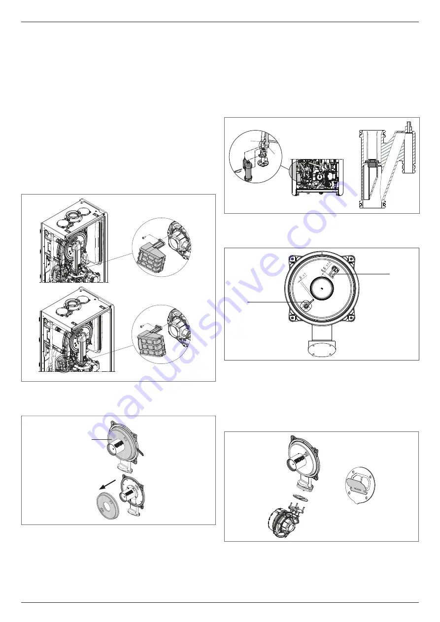
Cleaning the air filter
25kW
A
A
30-35kW
25kW
A
A
30-35kW
-
Unscrew the fixing screw
A
and remove the air filter.
-
Blow compressed air on the filter to remove any impurities.
-
In case of persistent dirt wash with water.
Replacing of the burner insulation panel
A
-
Unscrew the ignition/detection electrode fixing screws and remove it.
-
Lever the burner insulation panel (
A
) out using a blade (as shown in the figure).
-
Remove any residual fixing glue.
-
Replace the burner insulation panel.
-
The new insulation panel doesn’t need to be fixed with glue as its shape is designed to
couple perfectly with the heat exchanger flange.
-
Reassemble the ignition/detection electrode using the previously removed screws and
replacing the relative sealing gasket.
Cleaning the siphon
-
Disconnect the tubes (
A
) and (
B
), remove the clip (
C
) and remove the siphon.
-
Unscrew the bottom and top caps, then remove the float.
-
Clean the parts of the siphon from any solid residues.
b
Do not remove the safety shutter and its sealing gasket as their presence is in-
tended to prevent the escape of burnt gases into the environment in the event of
no condensation.
b
Once the operations have been completed, reassemble the components by operat-
ing in the reverse order to what is described, checking the floating seal and replace
it if necessary. If replacing the float gasket, make sure it is correctly positioned in its
seat (see figure in section).
b
At the end of the cleaning sequence, fill the siphon with water (see “2.12 Condensate
siphon”) before restarting the boiler.
-
At the end of the siphon maintenance operations, it is recommended to bring the boiler
to condensing mode for a few minutes and to check for leaks from the entire condensate
evacuation line.
A
C
B
Maintenance of the ionisation electrode
The detector electrode/ionisation probe play an important role in the boiler ignition phase
and maintaining an efficient combustion; in this regard, if it is replaced, it must always be
positioned correctly and the reference position indicated in the figure must be complied with.
detector electrode/
ionisation sensor
flame ignition
electrode
a
Do not sandpaper the electrode.
b
During the annual maintenance, check the state of wear of the electrode and replace
it if has badly deteriorated.
The removal and eventual replacement of the electrodes, including the ignition electrode,
involves also the replacement of the sealing gaskets.
In order to prevent operating faults, the detector electrode/ionisation probe should be
changed every 5 years since it is subject to wear during the ignition.
Check valve
D
The boiler has a check valve. To access the check valve:
-
remove the fan by unscrewing the 4 screws (
D
) fixing it to the conveyor
-
make sure there are no foreign material deposits on the membrane of the check valve
and if any remove them and checking for damage
-
check the valve opens and closes correctly
-
re-assemble the components in reverse order, making sure the check valve is put back
in the correct direction.
When there is maintenance work on the check valve make sure that it is positioned correctly
to ensure the system operates correctly and safely.
Содержание 20187642
Страница 1: ...Family KIS EN INSTALLER AND USER MANUAL...
Страница 33: ......
Страница 34: ......
Страница 35: ......
Страница 36: ...Cod 20187595 09 21 Ed 3...


