2.Mechanism
30
Touch panel
The touch panel of this machine uses a 4-wire resistive film method (low load resistive film analog 4-wire method). It can
detect two points for flick/drag/pinch-in/pinch-out operations. Resistive touch panel has been adopted in order to
allow operation with a prosthetic hand.
Basic Structure
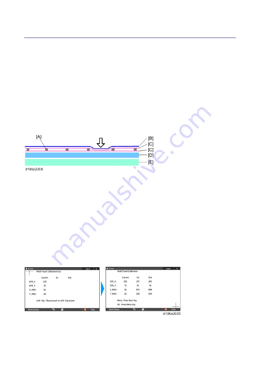
An analog 4-wire resistive film touch panel has 2 layers. Two materials (mainly film or glass) with transparent
conductive film (ITO) are attached such that the transparent conductive film layers face each other.
When the film is pressed with a finger or a pen, the transparent conductive films contact each other and the touch panel
operation is recognized.
Insulators (spacing dots) secure space between the two transparent conductive film layers to prevent short-circuiting.
Because the transparent conductive film has a uniform resistance characteristic, the resistance value reflects the distance
of contact.
[A]: Spacing dot
[B]: PET film
[C]: Transparent conductive film
[D]: Base glass
[E]: LCD panel
Self-Check (multi-touch calibration) mechanism
With the Multi-touch calibration in the self-check function, the touch panel is automatically calibrated using the results of
touches to the top left and bottom right positions.
The values of “EVR_X”, “EVR_Y”, “X_MAX”, and “Y_MAX” are used for internal processing. They do not indicate the
positions or distance of the touched points. There is no problem unless there is a huge difference between the values of
the first calibration and the second calibration.
Содержание M0A0
Страница 2: ......
Страница 10: ...8 ...
Страница 12: ......
Страница 30: ...2 Installation 18 Destination For printing images For operating NA 8 66 10 8 66 15 EU AP CHN 10 15 ...
Страница 33: ...2 Installation 21 6 Enter the password again 7 Press OK 8 Change the Administrator 1 login password ...
Страница 34: ...2 Installation 22 9 Enter the password 10 Press OK 11 Enter the password again ...
Страница 85: ...2 Installation 73 ...
Страница 127: ...4 Replacement and Adjustment 115 PCDU PCDU 1 Open the front cover A 2 Hold the grip to pull the PCDU A out ...
Страница 189: ...4 Replacement and Adjustment 177 ...
Страница 203: ...5 System Maintenance 191 SP Mode Tables See Appendices ...
Страница 229: ...5 System Maintenance 217 LDAP authorization information ...
Страница 344: ...7 Detailed Descriptions 332 side guides from side to side ...
Страница 358: ...7 Detailed Descriptions 346 ...
Страница 367: ...Latest Release Initial Release August 2016 Copyright c 2016 Ricoh Co Ltd MP 402SPF Machine Code M0A0 Appendices ...
Страница 368: ......
Страница 558: ......
Страница 560: ...2 Software Update Errors 57 Errors That Occur When the Control Panel Downloads Data from the Controller at Startup 62 ...
Страница 574: ...1 Replacement and Adjustment 16 7 LCD A 4 8 Microphone A cushioning 1 ...
Страница 622: ......
Страница 624: ... A Short Edge Feed SEF B Long Edge Feed LEF ...
Страница 626: ......
Страница 632: ...1 Installation 6 ...
Страница 703: ...4 Service Tables 77 0 Off 1 On change occurs such as an optical fiber line 5 7 Not used Do not change the settings ...
Страница 752: ...5 Detailed Section Descriptions 126 Report Sample ...
Страница 758: ...6 Specifications 132 Fax Unit Configuration Component No Remarks FCU 1 Speaker 2 ...
Страница 760: ......
Страница 762: ......
Страница 766: ...1 Detailed Descriptions 4 SW 1 SW 2 SW 3 Paper Size 7 H L H Half Letter SEF 8 H H H Paper cassette is not set ...
Страница 776: ...2 Replacement and Adjustment 14 4 Detach the paper size switch from the bracket A Hook x2 ...


