


12-8
Troubleshooting
RD 500 RD51
DOK-RD500*RD51*******-IB04-EN-P
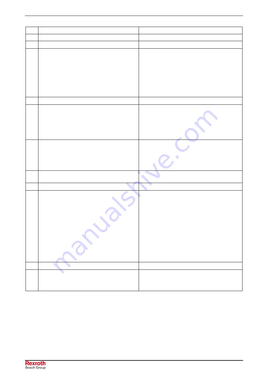
No.
Designation
Message
Cause
Remedy / comments
32
Overcurrent
Fault
Current limiting is active for a time which is longer
than that parameterized.
Check the setting of P0574!
The time duration of the uninterrupted current limiting
(D1678 = 1) can be set between 1 second and 100
seconds in 11 steps using P0574.
If current limiting is interrupted before the
parameterized time has expired (D1678 = 0), the time
counter is reset to 0 and then restarts at the next
current limiting.
If P0574 has been set to 0 (= continuous), then the
“Overcurrent” fault is output.
The peak current of the drive converter was exceeded
Causes outside the drive converter:
- Defective motor, invalid load, defective motor cable
- Setpoint step which is too fast
Disconnect the motor cable, enable the inverter. If the
fault no longer occurs, then it is highly likely that the
cause is outside of the drive converter.
Measure using the RDwin “Oscilloscope function”:
Parameter D1981 “f act from normalization”.
Cause in the parameterization:
The incorrect motor data were parameterized.
Only for option S sinusoidal filter: The pulse
frequency (P0026) is set to less than 8 kHz; thus, the
sinusoidal filter can oscillate and conduct high
currents.
Check the motor data in the Quick-Setup.
Set the pulse frequency in Quick-Setup (P0026) to 8
kHz or greater.
Cause inside the drive converter:
Defective power section transistor.
Please contact your customer service.
34
Safety Off (NAMUR)
Alarm / fault
The “Safety Off” fault message has been introduced
so that the drive converter fulfills the Namur Standard
(Namur is a Standards Committee for instrumentation
and control in the chemical industry). It is only
activated when P0057 is set to 1. The fault or alarm is
selected using P0571.
The fault is initiated using an external control signal,
which is connected to the digital input of the drive
converter.
The D parameter of the digital input is connected to
P0050.1.
The external control signal is used to positively
disconnect the drive from the line supply
(1 = operation; 0 = disconnected from the line
supply).
35
Motor overload
Alarm / fault
The electronic overload relay has responded (refer to
the function diagram “Modulation, measured value
sensing” or in the Operating Instructions Section 5 of
the basic programming “Thermal motor protection”).
Check P0566 “Overload protection threshold” to ensure
that it has been correctly set.
The type of response of the electronic overload relay
can be set using P0565: Disabled / Alarm / Fault.
Содержание RD 500 Series
Страница 32: ...2 12 Description of RD51 RD 500 RD51 DOK RD500 RD51 IB04 EN P...
Страница 174: ...5 34 Inverter Technical Data RD 500 RD51 DOK RD500 RD51 IB04 EN P...
Страница 248: ...9 4 Commissioning RD 500 RD51 DOK RD500 RD51 IB04 EN P...
Страница 274: ...14 6 Index RD 500 RD51 DOK RD500 RD51 IB04 EN P...
Страница 275: ......


