Rev.6.00 Oct.28.2004 page 101
of 1016
REJ09B0138-0600H
5.6.2
Block Diagram
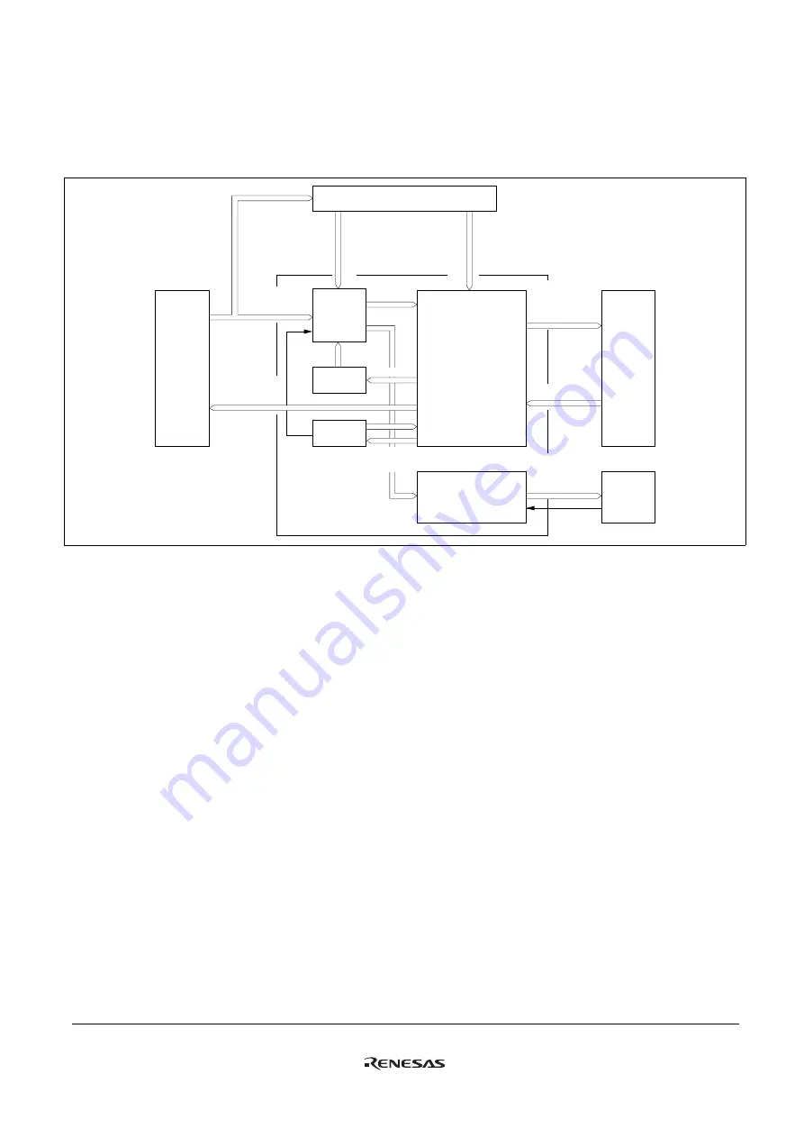
Figure 5-9 shows a block diagram of the DTC and DMAC interrupt controller.
DMAC
Selection
circuit
DTCER
DTVECR
Control logic
Determination of
priority
CPU
DTC
DTC activation
request vector
number
Clear signal
CPU interrupt
request vector
number
Select
signal
Interrupt
request
Interrupt source
clear signal
IRQ
interrupt
On-chip
supporting
module
Disable signal
Clear signal
Clear signal
Interrupt controller
I, I2 to I0
SWDTE
clear signal
Figure 5-9 Interrupt Control for DTC and DMAC
5.6.3
Operation
The interrupt controller has three main functions in DTC and DMAC control.
Selection of Interrupt Source: With the DMAC, the activation source is input directly to each channel. The activation
source for each DMAC channel is selected with bits DTF3 to DTF0 in DMACR. Whether the selected activation source is
to be managed by the DMAC can be selected with the DTA bit of DMABCR. When the DTA bit is set to 1, the interrupt
source constituting that DMAC activation source is not a DTC activation source or CPU interrupt source.
For interrupt sources other than interrupts managed by the DMAC, it is possible to select DTC activation request or CPU
interrupt request with the DTCE bit of DTCERA to DTCERF in the DTC.
After a DTC data transfer, the DTCE bit can be cleared to 0 and an interrupt request sent to the CPU in accordance with
the specification of the DISEL bit of MRB in the DTC.
When the DTC has performed the specified number of data transfers and the transfer counter value is zero, the DTCE bit
is cleared to 0 and an interrupt request is sent to the CPU after the DTC data transfer.
Determination of Priority: The DTC activation source is selected in accordance with the default priority order, and is not
affected by mask or priority levels. See section 7.6, Interrupts, and section 8.3.3, DTC Vector Table, for the respective
priorities.
With the DMAC, the activation source is input directly to each channel.
Operation Order: If the same interrupt is selected as a DTC activation source and a CPU interrupt source, the DTC data
transfer is performed first, followed by CPU interrupt exception handling.
Содержание ZTAT H8S/2357F
Страница 4: ......
Страница 28: ...Rev 6 00 Oct 28 2004 page xxiv of xxiv REJ09B0138 0600H...
Страница 82: ...Rev 6 00 Oct 28 2004 page 54 of 1016 REJ09B0138 0600H...
Страница 108: ...Rev 6 00 Oct 28 2004 page 80 of 1016 REJ09B0138 0600H...
Страница 364: ...Rev 6 00 Oct 28 2004 page 336 of 1016 REJ09B0138 0600H...
Страница 438: ...Rev 6 00 Oct 28 2004 page 410 of 1016 REJ09B0138 0600H...
Страница 566: ...Rev 6 00 Oct 28 2004 page 538 of 1016 REJ09B0138 0600H...
Страница 588: ...Rev 6 00 Oct 28 2004 page 560 of 1016 REJ09B0138 0600H...
Страница 688: ...Rev 6 00 Oct 28 2004 page 660 of 1016 REJ09B0138 0600H...
Страница 694: ...Rev 6 00 Oct 28 2004 page 666 of 1016 REJ09B0138 0600H...
Страница 708: ...Rev 6 00 Oct 28 2004 page 680 of 1016 REJ09B0138 0600H...
Страница 1044: ...Rev 6 00 Oct 28 2004 page 1016 of 1016 REJ09B0138 0600H...
Страница 1047: ...H8S 2357 Group H8S 2357F ZTATTM H8S 2398F ZTATTM Hardware Manual 2 6 2 Ote machi Chiyoda ku Tokyo 100 0004 Japan...


