background image

CHAPTER

6

Manual No. 016-0171-539 Rev. F

29

CHAPTER 6

SYSTEM MANAGER

The following sections provide information on using the System Manager utilities to view software and system 

hardware information, update system components, and activate codes for additional features.

SYSTEM MANAGER OVERVIEW

The system manager utilities allow the operator to review the software and firmware versions currently installed on 

various system devices, temporarily activate system features, and check status of a Slingshot Field Hub or request 

remote support.

To view information on software currently installed of available for use with this device

1. Touch the Administrator or User Panel along the top of the Main Panel display to expand the panel.
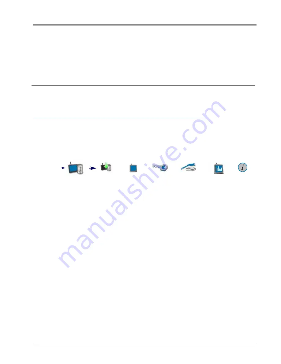
2. Select the System Manager utility. The following tabs will be available:

NOTE:

To transfer or copy files or settings using ROS, refer to Chapter 7, File Manager, for more information 

on file maintenance operations.

Software Update. 

The software update tab displays ROS software version information and allows the operator to 

update software or revert a previous version as needed. Refer to the ROS Information and Updates section on 

page 30 for additional information about using the software update tab.

Hardware Update. 

Firmware version information is displayed on the hardware update tab. This information may 

be useful for troubleshooting CAN systems or components. This tab also allows the operator to update the 

CAN system components as necessary to take advantage of new features available from Raven Industries 

Applied Technology Division. Refer to the Hardware Information and Updates section on page 33 for details on 

performing firmware updates via the ROS device.

Features Keys. 

The Features Keys tab displays permanent feature activations available. This tab also displays the 

time remaining for temporary authorization of ROS features. Temporary time codes entered on this prompt will 

only be available for a specific time period and will expire at a set time interval. Contact a local Raven dealer for 

assistance with permanent authorization of available ROS features.

Slingshot Field Hub. 

Select the Slingshot tab to view Field Hub wireless communication information or to enable 

a remote support session. For additional information on Slingshot services, refer to the ROS Slingshot Field 

Hub Calibration and Operation Manual or contact a local Slingshot dealer.

Hardware Information. 

The hardware information tab contains information about the field computer’s internal 

hardware states, usage statistics, diagnostics tools for CANBus, and network connectivity information.

Administrator 

or User Panel

System 

Manager

Software 

Update

Hardware 

Update

Feature Keys Slingshot

Field Hub

Hardware 

Information

License

Содержание viper

Страница 1: ...Viper Viper 4 Installation Operation Manual Manual No 016 0171 539 Rev F 11 16 E27652 Copyright 2016 ...

Страница 2: ...odifications or repairs made outside our facilities nor damages resulting from inadequate maintenance of this system As with all wireless and satellite signals several factors may affect the availability and accuracy of wireless and satellite navigation and correction services e g GPS GNSS SBAS etc Therefore Raven Industries cannot guarantee the accuracy integrity continuity or availability of the...

Страница 3: ...ation 11 Chapter 4 Navigation Overview 13 Home Screen and Panel Navigation 13 On Screen Keyboard 13 Status Header 14 Administrator or User Panel 15 Machine Configuration Panel 16 Product Configuration Panel 17 VT Panel 18 Job Profile Panel 18 Guidance Views and Widgets 19 View Selection 19 Widget Selection and Set Up 20 Alerts and Alarms 20 Chapter 5 Administrator and User Profiles 21 Overview 21 ...

Страница 4: ...er Overview 41 Using the File Manager 42 Using Filters and Renaming Files 42 Selecting Files 43 Grower Farm Field GFF Manager 43 Delete Files 45 File Export 45 Export Job Reports and Coverage Information 45 Export Other Field Operation Files 47 Export ISO Task Data 48 USB Import Manager 49 Import Grower Farm Field GFF Folder Structure 50 Import CAN Node Updates 51 Import Jobs 52 Import a Slingshot...

Страница 5: ...ation and Settings 87 Redetecting DGPS Devices 87 GPS Solution Information 87 Generic Differential Type Setting 89 Raven Receiver Settings 90 Redetecting DGPS Devices 90 Resetting Raven Receiver Defaults 90 Selecting a Differential Source 90 General Settings Tab 91 Setting GPS Message Outputs 91 GPS Receiver Information 92 Authorizing a DGPS Receiver Feature 92 Receiver Firmware Updates 93 Updatin...

Страница 6: ...16 CANbus Troubleshooting 118 Chapter 12 Product Panel and Configurations 119 Overview 119 Product Configurations 119 Create a New Product Configuration 119 Edit an Existing Product Configuration 120 Assign a Product Configuration for agX 120 Delete an Existing Product Configuration 120 Product Channel and Ingredient Set Up 121 Product Reporting Information 121 Mix Ratios and Ingredients 122 Chapt...

Страница 7: ...ry 141 Guidance Widgets 142 Implement Status and Control Widgets 143 Product Control Widgets 144 Bin Chain Widgets 145 Chapter 15 AB Guidance Utilities and Nudge Features 149 Guidance Patterns Overview 149 Straight AB Line 149 Pivot 149 Fixed Contour 150 Last Pass 150 Last Pass Swathing 151 Setting Guidance Paths 151 To Select a Guidance Pattern 151 Set a Straight AB Line 152 Setting Straight Line...

Страница 8: ...Scouting Feature 159 Scout Feature Setup 160 Recording a Field Feature 161 Auto Point Capture 161 Manual Point Capture 161 Street Maps 162 Street Maps for agX 164 Chapter 17 Tally Registers 167 Tally Register Prompt 167 Appendix A Calculating the Calibration Values 169 Speed Cal 169 Radar Speed Sensors 170 Wheel Drive Speed Sensor 171 Boom or Section Width Calibration 171 Liquid Control Systems 17...

Страница 9: ...draulic fluid may be extremely hot and under high pressure Perform any work on the hydraulic system in accordance with the machine manufacturer s approved maintenance instructions When installing hydraulics or performing diagnostics maintenance or routine service ensure that precautions are taken to prevent any foreign material or contaminants from being introduced into the machine s hydraulic sys...

Страница 10: ...re it at least every 30 cm 12in to the frame Follow existing harness as much as possible and use these guidelines Harness should not contact or be attached to Lines and hoses with high vibration forces or pressure spikes Lines and hoses carrying hot fluids beyond harness component specifications Avoid contact with any sharp edge or abrading surfaces such as but not limited to Sheared or flame cut ...

Страница 11: ...ater High pressure water sprays can penetrate seals and cause electrical components to corrode or otherwise become damaged When performing maintenance Inspect all electrical components and connections for damage or corrosion Repair or replace components connections or cable as necessary Ensure connections are clean dry and not damaged Repair or replace components connections or cable as necessary ...

Страница 12: ...tion and backlash of belts and chains Adjustment zones of adjustable brackets Changes of position in steering and suspension systems Moving linkages cylinders articulation joints attachments Ground engaging components For hose sections that move during machine operation Allow sufficient length for free movement without interference to prevent pulling pinching catching or rubbing especially in arti...

Страница 13: ...o simplify operation preparation Preconfigured product and job profiles allow the system user to set up operation or application details which allow the equipment operator to quickly select preconfigured settings for the product loaded and the job or operation to perform and begin field work without setting up the system The system administrator may view and use the above information from the job ...

Страница 14: ...SB flash drive The Slingshot web service is free and does not require any hardware or monthly subscriptions to utilize the reporting features of the web site With a Slingshot Field Hub files may be transferred to the equipment cab from a home or office PC and completed job reports may be transferred from the cabin to the home or office via the wireless network Visit the Slingshot web site for more...

Страница 15: ...ves as our customers see us and are eager to gather ideas on how we have been helping or how we can do better To serve you best please send an email with the following information to techwriting ravenind com Viper Viper 4 Installation Operation Manual Manual No 016 0171 539 Rev F Any comments or feedback include chapter or page numbers if applicable Let us know how long have you been using this or...

Страница 16: ...CHAPTER 2 8 Viper Viper 4 Installation Operation Manual ...

Страница 17: ...S device press the power button once The power status indicator will flash red and then should illuminate green If the status indicator stays red or does not illuminate contact a local Raven dealer for additional assistance NOTE Do not connect any USB drives or devices to the ROS device during the power up sequence VIPER 4 BUILT IN SELF TEST If the Viper 4 fails to display a picture on the screen ...

Страница 18: ...rder around the icon If the icon has a gold border it is an icon that can be selected and opened to make adjustments Icons with a gray or no border are informational and will not perform an action if pressed DEVICE SHUT DOWN When finished using the ROS device 1 Close any active jobs by selecting the home icon in the lower right corner of the display 2 Touch the administrator or user panel and sele...

Страница 19: ... a screen shot while not in a job quickly press the power button A Shutdown Requested window will open 4 Select Save Screen Shot 5 After capturing a screen shot export the data via file maintenance INITIAL MACHINE CONFIGURATION 1 Select the edit icon in the machine configuration panel and touch the add button 2 Use the on screen keyboard to enter a name for the machine or equipment configuration T...

Страница 20: ...cted to the CANbus at this time 8 Verify any multi channel nodes are configured correctly for the control channels necessary for the equipment during field operations Refer to Chapter 11 CANbus Device Set Up for details on readdressing product control nodes and configuring multi channel control nodes 9 Finish the machine configuration setup Refer to Chapter 8 Machine Panel and Configurations for d...

Страница 21: ...keyboard This keyboard is displayed when entering or modifying profile product or job names The following features may be used on the keyboard CHARACTER ENTRY When the keyboard is touched the character selected will display above the key If the character displayed is not the character intended for entry continue touching the screen while dragging to the correct character to enter The character wil...

Страница 22: ...l characters in the character entry field ACCEPT CANCEL Touch the key to accept the text or characters displayed in the character entry field The displayed text or characters will be entered in the selected text field on the previous screen Touch the key to return to the previous screen without entering the keyed text or characters LANGUAGE SELECT Pressing the language select button will change th...

Страница 23: ...dicator displays the current status of the position solution This indicator will display Green if the status of GPS is okay Yellow if an error or cautionary condition has been encountered Red if GPS is non functional Software Update Available One of these status displays will be available if a ROS update or feature unlock file is available The update will remain available even after the USB flash ...

Страница 24: ...entation updates may be made available periodically on the Raven Applied Technology web site www ravenhelp com NOTE Refer to Chapter 6 System Manager for more information on performing system and hardware updates FILE MANAGER Access the file manager to perform file maintenance access utilities for exporting and transferring job files and other data to and from the ROS device and to view the transf...

Страница 25: ... to modify or remove profiles to keep the ROS device updated for the equipment currently in the fleet or machine shed Refer to Chapter 8 Machine Panel and Configurations for additional information on selecting and modifying machine configurations and using the machine and implement garages PRODUCT CONFIGURATION PANEL The product configuration panel provides the following utilities for setting up c...

Страница 26: ...o access features such as the Raven ISO Product Control Raven ISO AutoBoom or various third party features connected to the ISOBUS communication network NOTE The VT panel will be available in the lower left corner of the main panel display only if an ISOBUS compatible ECU is detected by the ROS device Refer to Chapter 12 Virtual Terminal VT Panel for additional assistance with using the VT Panel o...

Страница 27: ...rify the job settings and select start ROS also provides utilities to help sort and filter the items displayed in the job profile panel to help the operator quickly locate and select the correct profile or previous operation NOTE Setting up a job profile is not a requirement and is designed as a Grower function The default Start Job profile allows a user to quickly start a job and allows the user ...

Страница 28: ...various types of field operations equipment or applications The operator may select as few or as many widgets as desired or necessary to perform tasks in the field Each customized layout may be saved to allow the operator to quickly switch from one layout to the next with a few screen touches complete a specific task and then return to the desired operation screen For example during tillage operat...

Страница 29: ...mation with completed job reports for review by an equipment owner or manager A system administrator is also able to review field area covered by each active profile if multiple profiles were active during a single field operation This information is potentially useful to identify operator training needs improve operator performance or make adjustments for future field operations ADMINISTRATOR PRO...

Страница 30: ... button to create a new user profile 5 Refer to the User Profile Settings Definition section on page 23 for details on completing the profile information for the new user profile EDITING OR DELETING USER PROFILES To edit or delete User Profiles 1 Touch the Administrator Panel along the top of the main panel display and select the User Profile button 2 Touch the Administrator Options tab at the far...

Страница 31: ...de button in the lower left corner of the display 3 Select the option to Restart with the Demo Mode Enabled The ROS device will restart with the demonstration mode features enabled 4 Perform the above procedure again to toggle the demonstration mode off NOTE There is a Viper 4 Setup Demo on www ravenhelp com USER PROFILE SETTINGS DEFINITION Each user profile provides fields for entering contact in...

Страница 32: ...fields LOCATION INFORMATION TAB The location information tab provides fields for company contact information and desired display language To access location information 1 Touch the Administrator or User Panel along the top of the Main Panel display and select the User Profile button 2 Touch the Location Information tab on the General User Settings prompt The following fields will be available Comp...

Страница 33: ...ht savings time adjustments if the local time zone jurisdiction observes daylight savings time SYSTEM PREFERENCES TAB The System Preferences tab provides access to settings to customize the ROS device display and operation To adjust system preferences 1 Touch the Administrator or User Panel along the top of the main panel display and select the User Profile button Unit System Units Metric centimet...

Страница 34: ...gnition Without the appropriate harness the power down feature will have no affect on operation of the ROS device Calibrate Touch Screen Touch the calibrate touch screen button to begin the touch screen calibration process on Viper 4 ALARM SETTINGS TAB To edit Alarm Settings NOTE Audible and pop up alarms will be triggered based upon the product control user settings Refer to the Product Control U...

Страница 35: ... access or operation Set PIN The administrator PIN field is displayed below the Require PINs option Enter the desired administrator PIN or personal identification number used to log into the administrator profile NOTE Raven will not be able to recover or reset the administrator PIN if the default 1111 is changed Be sure to write down the administrator PIN and store it in a safe place to ensure the...

Страница 36: ... a low rate condition Rate Colors Touch the High OK and Low rate colors to select custom rate colors for the user Zero Rate Tolerance Dry or granular application systems rely upon one or more encoders to monitor the application system and measure the rate of product being applied In some instances such as when driving through zero rate zones or with the application system toggled off the encoders ...

Страница 37: ...ion is displayed on the hardware update tab This information may be useful for troubleshooting CAN systems or components This tab also allows the operator to update the CAN system components as necessary to take advantage of new features available from Raven Industries Applied Technology Division Refer to the Hardware Information and Updates section on page 33 for details on performing firmware up...

Страница 38: ...te In the event that an update to ROS provides undesirable operation the device will store the last software version installed and allow the operator to revert to the version displayed in this field Factory Reset The factory reset feature may be used to revert the device to a factory condition Only perform this procedure if instructed by a dealer or service technician All settings and user files w...

Страница 39: ...w updating the ROS device may affect system operation Please review these notes and be sure to follow any special instructions 5 At the bottom of the release notes page select Download Update to start the software download 6 Select Save to save the software to the home or office computer Select a commonly used download directory or a destination which will be easy to locate after the download comp...

Страница 40: ...the ROS device NOTE Review the ROS Download Example section on page 30 for more information on the folder structure required for performing the update 2 Once the update file is detected on the USB drive the Update Available status will be displayed in the upper right corner of the main panel display and the update file will be copied to the ROS device 3 Remove the USB flash drive The update still ...

Страница 41: ...n information will be displayed in this column Program Number The program number is used to identify the node on ROS NOTE The program number displayed on the hardware update tab does not reflect the program identified on the physical serial number tag affixed to the node from the factory Current Version The firmware currently installed on the node will be displayed in this column Newest Version If...

Страница 42: ...age may have important information about how updating the ROS device may affect system operation Please review these notes and be sure to follow any special instructions 5 At the bottom of the release notes page select Download Update to start the firmware download 6 Select Save to save the firmware to the home or office computer Select a commonly used download directory or a destination which wil...

Страница 43: ... drive onto the ROS device before the firmware updates may be applied to nodes connected to the system using the System Manager utility Refer to Import CAN Node Updates section on page 51 for assistance copying CAN Node Update files The following procedure is only applicable to Raven CANbus components ISOBUS components cannot be updated via the ROS device To apply a firmware update to a CANbus sys...

Страница 44: ... dealer or the Raven Technical Support Center for additional assistance with appropriate program numbers for recovering a CANbus node To attempt to recover a CANbus node on which a failed update has occurred 1 Insert the USB flash drive with the firmware update files in the required folder into the ROS device NOTE Review the CANbus Firmware Download Example section on page 33 for more information ...

Страница 45: ...after the activation key request form is submitted 7 Copy the feature package to the USB flash drive used with the ROS device The feature package must be copied to the following directory on the flash drive USB Drive Name Raven FeatureUnlocks 8 Connect the USB flash drive to the ROS device The feature package will automatically install 9 Restart the ROS device when prompted to make the new feature...

Страница 46: ...us step 5 Touch Renew Time and enter the temporary service code to add time to the temporary features time remaining SLINGSHOT FIELD HUB The Slingshot tab provides access to Slingshot Field Hub information and will be used when requesting remote support For additional information on using the Slingshot Field Hub with the ROS device refer to the ROS Slingshot Field Hub Calibration and Operation Man...

Страница 47: ...tion on the switch power camera power camera fault and FPGA fault USAGE Provides CANBus information such as warning counts bus off counts and on error states NETWORKING Provides information on the IP address gateway and the interface name LICENSE To review and accept the ROS End User License Agreement EULA at any time 1 Touch the Administrator or User panel along the top of the Main Panel display ...

Страница 48: ...CHAPTER 6 40 Viper Viper 4 Installation Operation Manual ...

Страница 49: ...stance with using the file manager or the Grower Farm Field GFF Manager section on page 43 for details on managing the GFF for file structure USB Import Manager Tab The USB import manager tab allows the operator to find and transfer files from a connected USB flash drive to the ROS device Review the USB Import Manager section on page 49 for assistance using the USB manager File Transfer History Ta...

Страница 50: ... page 33 for more information on downloading and applying CAN node firmware updates USING FILTERS AND RENAMING FILES To use the file filters or rename files 1 Touch the Administrator or User Panel along the top of the Main Panel display to expand the panel 2 Select the File Manager utility and touch the File Manager tab The File Manager tab will display a list of the following file types currently...

Страница 51: ...all button at the top of the list to remove all files at once 6 Proceed to the Manage Grower Farm Field GFF Information section on page 44 or the Delete Files section on page 45 for assistance with performing these file management procedures GROWER FARM FIELD GFF MANAGER ROS offers a Grower Farm Field GFF utility to create and manage GFF information right on the ROS device NOTE The GFF Manager is ...

Страница 52: ...Manager utility and press the File Manager tab File Manager will open and display a list of files currently stored on a ROS device 3 Touch the Edit button at the top of the Selected Files list 4 Select the Edit button displayed at the top of the GFF display 5 Use the file browser to select the desired grower farm or field entry to edit 6 With the appropriate entry selected touch the Edit button To...

Страница 53: ...s file transfer A Slingshot Field Hub and wireless service contract will be required to send files to the Slingshot web service from the vehicle cabin Contact a local Slingshot dealer or refer to the ROS Slingshot Field Hub Calibration and Operation Manual for additional assistance with using the Slingshot Field Hub for transferring job files EXPORT JOB REPORTS AND COVERAGE INFORMATION ROS is capa...

Страница 54: ...der Structure jdp Select this option to create a job data package jdp on the USB flash drive with the grower farm field GFF file structure The jdp file may be transferred to a Slingshot viewer or user account to review job information or create job reports or to another ROS device via the USB flash drive to continue the job NOTE While the GFF file structure is transferred to the USB flash drive us...

Страница 55: ...THER FIELD OPERATION FILES ROS is capable of exporting the following files used during field operations Prescription Rx Maps shapefile format Scout Groups sct Guidance Lines ab CAN Node Updates Screen Shots Core Dumps Log Files If desired files can be exported for archiving or be transferred for use on another ROS device The following procedures are for exporting field operation files to a connect...

Страница 56: ... inherently associated with the field operation files if transferred to another ROS device To reassociate the jdp with the GFF information import the GFF structure via the USB manager and then reassign the jdp to the GFF using the File Manager tab Review the Import Grower Farm Field GFF Folder Structure section on page 50 for assistance with importing the GFF information and the Grower Farm Field ...

Страница 57: ...t export media The GFF data will export to the USB device in an ISO XML format NOTE ISO TASKDATA can only be edited on the device the TASKDATA was created on USB IMPORT MANAGER The USB Import Manager utilities allow the machine operator to select and import the following file types from a USB flash drive connected to the ROS device Grower Farm Field Folder Structure CAN Node Updates Jobs Slingshot...

Страница 58: ...one file type may be imported at a time Perform the import procedure multiple times in order to import multiple file types 6 Touch the next button on the USB manager tab The USB flash drive and folder structure will display 7 Use the displayed browser to locate the Grower folder within the GFF folder structure to be imported For Example USB Drive Name Raven GFF Grower Name NOTE When importing the ...

Страница 59: ... of the Main Panel display to expand the panel 3 Select the File Manager utility and touch the USB Manager tab 4 Touch the USB drop down and select the connected USB flash drive from which to import files 5 Touch the File Type drop down and select the CAN Node Update option 6 Touch the Next button on the USB manager tab The USB flash drive and folder structure will display 7 Use the displayed brow...

Страница 60: ...mported via a Slingshot Archive ssa file type Refer to the Import a Slingshot Archive section on page 53 for assistance importing this file type 1 Insert the USB flash drive with the job profile 2 Select the Administrator or User Panel along the top of the Main Panel display to expand the panel 3 Select the File Manager utility and touch the USB Manager tab 4 Touch the USB drop down and select the...

Страница 61: ...ncel button to return to the USB Manager tab 11 Touch the Import button to begin the file transfer process IMPORT A SLINGSHOT ARCHIVE To import a Slingshot Archive ssa file from a USB flash drive 1 Insert the USB flash drive containing the Slingshot Archive file 2 Touch the Administrator or User Panel along the top of the Main Panel display to expand the panel 3 Select the File Manager utility and...

Страница 62: ... the USB flash drive The Import Files prompt will display 10 Verify the list of files to be imported is correct If the list requires further configuration touch the Cancel button to return to the USB Manager tab 11 Touch the Import button to begin the file transfer process IMPORT PRESCRIPTION RX MAPS NOTE Prescription maps may also be imported via a Slingshot Archive ssa file type Refer to the Imp...

Страница 63: ...atively touch the Select All option at the top of the file list to select all files currently displayed 9 With at least one file selected select one of the following import actions Copy create a duplicate of the selected information on the ROS device Move import the selected information to the ROS device and remove the information from the USB flash drive The Import Files prompt will display 10 Ve...

Страница 64: ...tRoot folder which contains the scout group to be imported Scout group files currently stored on the USB flash drive will be found within the GFF folder structure and are displayed in the lower portion of the USB manager tab For Example USB Drive Name Raven GFF Grower Name Farm Name Field Name scoutRoot Scout Group Name 9 Touch the box displayed to the left of the listed file names to select speci...

Страница 65: ...es option NOTE Only one file type may be imported at a time The import procedure will need to be performed multiple times in order to import multiple file types 6 Touch the Next button in the lower right corner of the USB manager tab The USB flash drive and folder structure will display 7 Use the browser displayed to locate and select the abLines folder which contains the line to be imported Guida...

Страница 66: ...F data or field boundaries 12 Refer to the ROS Slingshot Field Calibration and Operation Manual for additional information on using a Slingshot Field Hub with the ROS device FILE TRANSFER HISTORY If a Slingshot Field Hub is connected with the ROS device for wireless communication the File Transfer History tab may be used to track and review transfer history via the Field Hub Refer to the ROS Sling...

Страница 67: ...File Manager 59 FILE MANAGER ...

Страница 68: ...CHAPTER 7 60 Viper Viper 4 Installation Operation Manual ...

Страница 69: ...configurations ROS will attempt to detect and select the machine configuration to which the device is connected Specific machine configurations also allow an operator to select various tractor implement combinations and quickly reconfigure ROS for operation on various equipment throughout the season If a machine configuration does not exist for the detected system ROS will prompt the user to modif...

Страница 70: ...configuration will need to be modified or adjusted when ROS first detects the CANbus system to be associated with the machine configuration Refer to the Edit an Existing Machine Configuration section on page 63 for assistance with modifying an existing machine configuration To create a new Machine Configuration 1 Touch the Machine Panel to display the available machine configurations 2 Touch the A...

Страница 71: ...lected garage to manage available tractor self propelled or implement profiles Refer to the Self Propelled Machine Profiles section on page 64 or the Tractor Profiles section on page 67 for assistance with creating or editing a machine profile or the Pull Type Implement Profiles section on page 69 for assistance with creating or editing implement profiles DELETE AN EXISTING MACHINE CONFIGURATION N...

Страница 72: ...h as sprayers spreaders harvesters or swathers are configured with an implement fixed or attached on the vehicle NOTE Self propelled machine profiles cannot be assigned to a machine configuration with an additional pull type implement such as a disk or plow tool bar pull type applicator etc CREATE A NEW MACHINE PROFILE To access the machine garage and create a new self propelled machine profile 1 ...

Страница 73: ...ing upon the equipment offered from the manufacturer or the optional features installed on the machine for which the profile is being created select no options to enter custom section profiles later in this procedure a specific option matching or close to the OEM equipment currently installed on the machine multiple or all equipment options if the machine offers multiple equipment configurations u...

Страница 74: ...groups EDIT THE CURRENT MACHINE PROFILE To make adjustments to the current machine profile 1 Touch the Edit icon in the Machine Panel to view the machine devices 2 Touch the Machine Profile button to access the profile settings 3 Select the General Information tab and enter identification information for the machine Refer to the General Information Tab section on page 77 for additional information...

Страница 75: ...mplement Profiles section on page 69 for more information on pull type implement profiles NOTE Tractor profiles may be assigned to a machine configuration with one or more pull type implement profiles such as a tool bar pull type applicator or air seeder cart and drill etc CREATE A NEW MACHINE PROFILE To access the Machine Garage and create a new tractor machine profile 1 Touch the Machine Panel t...

Страница 76: ... section on page 79 for assistance with measuring the machine wheel base 14 Press Done Refer to the Pull Type Implement Profiles section on page 69 for more information on setting up implement profiles for use with the tractor profile EDIT THE CURRENT MACHINE PROFILE To make adjustments to the current machine profile 1 Touch the Edit icon to view the machine devices 2 Touch the Machine Profile but...

Страница 77: ...red 4 From the list of available machine profiles select the machine 5 Press the Delete button to remove the machine profile from the Machine Garage PULL TYPE IMPLEMENT PROFILES Profiles for pull type implements such as plows disks pull type applicators planters air seeder cart drill or other tool bars are configured as an addition to a separate tractor profile Refer to the Tractor Profiles sectio...

Страница 78: ...riate selections are set touch the OK button 10 The General Information tab allows the operator to enter or modify implement information Touch the information fields and use the on screen keyboard to enter general information about the implement for identification purposes If a preset implement profile was selected verify the information displayed and make adjustments if necessary 11 Enter the fro...

Страница 79: ...or profile information Refer to the Tractor Profiles section on page 67 for more assistance with the tractor information 8 Use the page navigation buttons at the bottom of the machine profile tabs or swipe from left to right to access the machine configuration tab 9 Use the machine configuration tab to modify the configuration information or override the implement width or offset information used ...

Страница 80: ...b NOTE When using an implement profile assigned to a machine configuration use the page navigation at the bottom of the tab or swipe across the screen to access additional implement profiles without backing out to the machine configuration panel The Equipment tab displays the name or description type and overview of the configured sections and section labels for any configured section groups 4 To ...

Страница 81: ...e overall offset of the implement e g spray boom spread pattern knives or shanks etc from the center of the machine or implement pivot point as necessary a Select the left right offset direction and select the offset distance field and use the on screen keypad to enter the distance from the center of the implement pivot point to the center of the section group Refer to the Equipment Setup Measurem...

Страница 82: ...ngs for each section in the section group Once the section labels width and wired as settings are configured ROS may be used to automatically calculate and set the section offsets for the group To automatically calculate section offsets 1 Verify that the section width field for each section in the group has been entered correctly 2 Touch the Calculate Offsets button to automatically align sections...

Страница 83: ... implement garage MACHINE DEVICES Touch the machine devices button to expand the machine devices panel and access additional GPS serial and CANbus device settings MACHINE AND IMPLEMENT PROFILES Machine profiles store information such as the machine geometry and GPS antenna mounting position which will be used to provide guidance during field operations To complete the machine configuration machine...

Страница 84: ...e Edit Profile Select the Edit button in the upper right corner of the machine or implement garage to edit the selected profile Delete Profile Touch the Delete button to remove the selected machine or implement profile from the garage Any machine configurations associated with the profile may be incomplete until another profile is assigned to replace the deleted profile MACHINE CONFIGURATION TAB 1...

Страница 85: ...ield operations Width Enter the desired override width for calculating and displaying guidance paths during field operations NOTE The override width does not modify configured section information Coverage of active sections will be displayed and mapped as configured for the machine profile OFFSET INFORMATION Left Right Override Direction Touch the direction drop down and select the direction in wh...

Страница 86: ...described below and use the on screen keyboard to edit the displayed profile information Type A description of the type of machine or implement used with the selected profile Sub Type The sub type field offers an additional line of equipment description to help identify the appropriate equipment with which the profile should be used Manufacturer Name or description of the original equipment manufa...

Страница 87: ...d parallel with the direction of travel Hitch The hitch distance should be entered if the implement or cart will be towed between the machine and another implement during field operations Enter the distance in inches centimeters from the implement rear axle to the hitch point on the implement or cart The hitch distance must be measured parallel with the direction of travel MEASUREMENTS TAB NOTE Me...

Страница 88: ...ue is the measurement from the ground to the bottom of the GPS antenna The height value will only be necessary if a tilt corrected DGPS signal is provided to the field computer MACHINE AND HITCH MEASUREMENTS The machine measurement settings provide information about the machine geometry used by ROS to map the vehicle position during field operations and create coverage or as applied data for field...

Страница 89: ...N GROUP DISPLAY The following information about configured section groups will display on the Equipment tab Section Group Name The name or description assigned to the section Refer to the Equipment Setup General Information Tab section on page 82 for more information on entering section group names or descriptions displayed in this area Section Group Type The selected or entered section type for t...

Страница 90: ...DEFINITIONS Review the following sections for additional assistance with entering section group information and setting up section configurations within a section group EQUIPMENT SETUP GENERAL INFORMATION TAB 1 Touch the Edit icon in the Machine Panel to view the machine devices 2 Touch the profile buttons for the machine or implements currently assigned to the machine configuration to view the ge...

Страница 91: ...ion group REPORTING INFORMATION The lower portion of the general information for the equipment setup or section groups allows the operator to enter the following information as applicable to the field operation NOTE The following fields are for report notation or display information purposes only and will not set or adjust any values or control system characteristics for an application control sys...

Страница 92: ...ine of the machine or implement Left Right Offset Distance Select the offset distance field and enter the distance from the center line of the machine or implement to the center of the section group in inches centimeters The left right offset distance must be measured perpendicular to the direction of travel Fore Aft Offset Direction Touch the fore aft offset direction drop down and select the pos...

Страница 93: ... Set and verify width values for all sections in the group See the Equipment Setup Sections Tab section on page 84 for details on setting the width value for each section 2 Touch the Calculate Offsets button ROS will automatically set the left right offsets for a standard section configuration 3 If necessary manually adjust the fore aft or left right offset direction and distance values to customi...

Страница 94: ...ection on page 76 for additional assistance SECTION OFFSETS Left Right Offset Direction Touch the left right offset direction drop down and select the direction from the center of the boom or implement to the center of the section Left Right Offset Distance Select the offset distance field and enter the distance from the center of the boom or implement to the center of the section in inches centim...

Страница 95: ...es Check all cabling connections and refer to the Serial Device Detection section on page 105 for assistance with redetecting and reinitializing serial communications GPS SOLUTION INFORMATION 1 Touch the Edit icon in the Machine Panel to view the machine devices 2 Locate and select the GPS module The GPS Global Settings prompt will display 3 Press the GPS Configuration icon to the right of the des...

Страница 96: ...reenwich Mean Time Messages Displays what NMEA messages are being received by ROS and the frequency at which they are being received GPS REVERSE SENSING NOTE The GPS based reverse sensing feature is not available if a Raven SmarTrax steering node with terrain compensation capabilities is detected on the CANbus and the Terrain Compensation feature on the node is activated Touch the GPS Reverse Sens...

Страница 97: ...oting or correcting the current condition GENERIC DIFFERENTIAL TYPE SETTING When using a Generic source e g GPS from a non Raven receiver or GPS routed through an optional SmarTrax system etc for a differential solution the operator must set the type of differential corrections used for a position solution ROS will use this setting to help monitor status of GPS corrections during field operations ...

Страница 98: ...S module The GPS Global Settings tab will open 3 Press the GPS Configuration button to the right of the desired receiver The differential settings prompt tab will display 4 Touch the Restore Receiver Defaults button NOTE The Restore Receiver Defaults button will not be available if a compatible receiver is not detected SELECTING A DIFFERENTIAL SOURCE To configure the differential source used for p...

Страница 99: ...TK Timeout If the unit it RTK capable this will be shows as RTK timeout For other units it will be Differential Timeout Set the Differential RTK Timeout value to the desired time to wait before the receiver will switch to the next available differential correction source For example if the receiver is configured to use an RTK correction source and RTK correction messages for this source are not av...

Страница 100: ...GPS RECEIVER INFORMATION To access additional information for a compatible Raven receiver using the ROS device 1 Touch the Edit icon in the Machine Panel to view the machine devices 2 Locate and select the GPS module The GPS Global Settings prompt will be displayed 3 Click the Configuration button to the right of desired receiver The Differential Settings tab will open 4 Touch the GPS Information ...

Страница 101: ...lly on the Raven Help web site www ravenhelp com The following items will be required to update the integrated receiver ROS device with an integrated receiver serial number starting with BFN Home or office PC or laptop with Microsoft Windows operating system and the WinLoad utility NOTE WinLoad is not compatible with 64 bit operating systems Serial cable USB to serial adapter optional ROS device c...

Страница 102: ...rated receiver 1 On a computer visit the Raven Help web site 2 Select the Product Support menu and locate the specific ROS device to be updated 3 Select the Software Updates option to view available software options Unless otherwise instructed by a support or service technician it is recommended to download the latest ROS version 4 Select View to review the software release notes for the new softw...

Страница 103: ...ettings 6 In the Com Port Setup prompt select the com port on the PC or laptop connected to the GPS out connector Refer to the operating system help for assistance determining which com port is connected to the ROS device cable 7 Set the Download Baudrate to 115200 8 Set the Connect Baudrate to 9600 and click OK 9 Click File in the upper left corner of the WinLoad window and select File Open 10 Us...

Страница 104: ...nual or contact a local Raven dealer for more information on capabilities of a specific ROS device or display RTK The Real Time Kinematic RTK correction type uses a Slingshot Field Hub a Continuously Operating Reference Station CORS network or a traditional base station system for a position solution These systems use a ground reference station to provide highly accurate corrections NOTE The RTK o...

Страница 105: ...rrections capability GLONASS If the ROS device supported receiver is capable of using the GLONASS satellite constellation this mode will be displayed in the lower left corner of the Differential Settings tab The optional GLONASS Global Navigation Satellite System satellite constellation may be unlocked to increase the number of satellites visible at any given time This feature may help to improve ...

Страница 106: ...NOTE Higher values will allow the receiver to converge faster but will allow more horizontal position error Smaller values will provide more accurate position but will take longer to converge and are more likely to lose a converged status during field operations The following information is displayed in the Subscription Status area of the Differential Settings tab when configured for GS Satellite ...

Страница 107: ...hen configuring a compatible receiver and using the OmniSTAR correction service OmniSTAR Satellite Select the specific satellite for use with OmniSTAR correction services for the area of operations Custom Satellite Enable This option allows the operator to enable a custom satellite for use with the OmniSTAR subscription Only enable this feature when instructed by an OmniSTAR technician Custom Sate...

Страница 108: ...ingshot field hub Distance This value displays the baseline or distance from the vehicle position to the base station antenna Latitude Longitude and Elevation The bottom portion of the prompt when set for an RTK correction source will display the geographic coordinates and elevation of the current base station GLONASS If the ROS device offers an integrated receiver capable of using the GLONASS sat...

Страница 109: ...ed in the lower portion of the GPS Output tab Touch the slider buttons and drag the button to adjust the slider to set the desired message rates Set the slider to 0 Hz to shut off the corresponding message Shut off any messages not required for output to other system components to ensure the best possible performance during field operations Port Baud Rate Touch the baud rate drop down field and se...

Страница 110: ... ID etc Differential Age This value is the age of the last differential update The differential age should not rise above a few seconds to ensure accurate position corrections during field operations HDOP Horizontal Dilution of Precision HDOP is a value used to indicate the geometry of the satellite constellation used in the position solution High HDOP values indicate that the visible satellite co...

Страница 111: ...he Differential Settings tab will open 4 Touch the Authorization Code Entry tab Authorization Code Field Review the information displayed on the Authorization Code Entry tab before entering the code received from a local Raven dealer to activate or unlock optional features of the selected Raven receiver Review the Authorizing a DGPS Receiver Feature section on page 92 for assistance with obtaining...

Страница 112: ...CHAPTER 9 104 Viper Viper 4 Installation Operation Manual ...

Страница 113: ...splay the following information for each detected device serial device name automatic or user configured communication settings current active communication COM port the input baud rate at which the ROS device is attempting to communicate with the device NOTE The COM port displayed on the Serial Devices tab does not reflect the cable connector label to which the device may be connected Redetect th...

Страница 114: ...e devices 2 Locate and select the Light Bar module 3 Select the Light Bar tab to access the following light bar display settings Path Deviation Sensitivity The path sensitivity may be adjusted for the type of field operation being performed and allows the operator to adjust how the distance from the displayed guidance path will be displayed by the light bar Select the fine standard and coarse pres...

Страница 115: ...NOTE When connecting a Raven RGL series light bar to the ROS device it is recommended to set the light bar to a static baud rate This will ensure that the serial device is detected when the ROS device scans for serial devices on power up If it is not possible to set the RGL lightbar to a static baud rate lock ROS to a static baud rate for the port the RGL is connected to WEATHER STATION DEVICES Th...

Страница 116: ...reenSeeker activation code will be required to unlock the GreenSeeker interface and features Contact a local GreenSeeker or Raven dealer for additional information or assistance GREENSEEKER COMMUNICATION SETTINGS NOTE Only the GreenSeeker serial device communication settings are configurable via the ROS device Review the GreenSeeker operation documentation for additional assistance with system cal...

Страница 117: ...eld operations On power up the ROS device should automatically establish communication with the boom speed node any AccuBoom AutoBoom or SmarTrax nodes if installed and multiple product control channels via the CANbus NOTE Product nodes may need to be readdressed before the ROS device will be able to detect each control channel on the CANbus See the Readdressing Control Channels section on page 11...

Страница 118: ...e To restart CANbus network communications 1 Touch the Edit icon in the Machine Panel to view the machine devices 2 Locate and select the CAN System module The CAN System tab will be displayed 3 Touch the Retry CAN button at the bottom of the CAN System tab to manually restart CANbus communication 4 Confirm the restart of the CANbus system ROS will restart the CANbus and return to the CAN system t...

Страница 119: ...ontrol channels will need to be addressed single or multi product nodes motor control planter or seeder control nodes etc When readdressing multi channel control nodes configure the number of channels on the node prior to readdressing the CANbus Review Multi Channel Node or ECU Configuration section on page 110 for details on configuring multi channel control nodes RAVEN CANBUS NETWORK 1 Touch the...

Страница 120: ...orized Raven service technician To reset the CANbus nodes to default settings 1 Touch the Edit icon in the Machine Panel to view the machine devices 2 Locate and select the CAN System module The CAN system tab will display 3 Touch the Reset CAN button at the bottom of the CAN system tab to reset all CANbus product control nodes to default settings 4 Confirm the CANbus reset ROS will restore the CA...

Страница 121: ... calibration values are recommended for initial system set up These values are good starting points and generally yield adequate results however the speed cal should be refined for the specific system and equipment Refer to Appendix A Calculating the Calibration Values for instructions on refining the speed calibration NOTE The GPS speed over CANbus feature is only available with specific Raven sp...

Страница 122: ...ided to the ROS device to accurately adjust rate control systems map coverage and create application reports for the product coverage One of the following switch box options will be required to provide section status during field operations EXISTING EQUIPMENT SWITCHES Implement section status may be wired into the ROS device from existing switch panels on many implements The switch panel must prov...

Страница 123: ...ssign sections to configured switches touch the Auto Map Sections button in the lower right corner of the display This button will only be available if the number of configured implement sections matches the number of switches NOTE Verify the section assignments before starting an actual field operation with the automatic section assignments To manually set up the physical section switch box assig...

Страница 124: ...Switch Select this option to allow the operator to use an on screen master switch widget to toggle the implement status With this option selected the operator will need to add the master switch widget to the guidance display in order to toggle coverage history on or off during field operations NOTE The on screen master switch is only capable of toggling coverage for a single section or full implem...

Страница 125: ... NOTE If the on screen switch box has been previously configured a summary of the switch box assignments will display 3 Touch the Edit icon in the upper right corner of the Summary screen and touch the On Screen Switch Box tab 4 To automatically assign sections to configured switches touch the Auto Map Sections button in the lower right corner of the display This button will only be available if t...

Страница 126: ...tch function the section must first be unassigned from the current switch CANBUS TROUBLESHOOTING Although the control algorithm is located within the CAN node all of the same troubleshooting techniques that are used in a traditional hard wired or serial control systems still apply to a CAN system and the behavior of the system remains the same Flow and speed sensors as well as the control valve an...

Страница 127: ...RODUCT CONFIGURATIONS Product configurations save information on products assigned to each control channel and may be used to quickly set up the Raven OS for common or various input or application operations The product configuration information may be used to enhanced job reporting information and allows improved product information to be saved changed and used quickly and easily CREATE A NEW PRO...

Страница 128: ...be modified 3 Touch the Edit button along the right side of the display to edit the selected product configuration The product configuration prompt will be displayed 4 Edit the existing information for each control channel as necessary to modify or adjust the configuration for the field operation needs Refer to Product Channel and Ingredient Set Up section on page 121 for additional information on...

Страница 129: ...figuration panel and select a product configuration to modify or create a new configuration NOTE Refer to the Create a New Product Configuration section on page 119 or the Edit an Existing Product Configuration section on page 120 to create or edit a product configuration 2 Touch the Edit button in the Product Configuration panel to edit the selected product configuration 3 Select a channel indica...

Страница 130: ...he Product Configuration panel and select a product configuration to modify or create a new configuration NOTE Refer to the Create a New Product Configuration section on page 119 or the Edit an Existing Product Configuration section on page 120 to create or edit a product configuration 2 Touch the Edit button in the Product Configuration panel to edit the selected product configuration If the cont...

Страница 131: ... to help locate and select the desired product for the ingredients list and touch the Done button to add the selected product to the ingredients list NOTE The selected product will also be added to the Favorite Products list To create a new product or ingredient not available in the product database touch the Add button at the bottom of the Reference Products prompt Proceed with the procedure desc...

Страница 132: ...roduct name or description already in the product database NOTE Use the product Name filter option to the right of the Name drop down list to filter the product database information This feature may be useful when adding a new product based upon a product or product line already in the database 8 Touch the Liquid Dry drop down and select the type of product to be configured 9 Touch the Units drop ...

Страница 133: ...ce regularly to keep device resources available for active field operations Transfer completed job files to a home or office PC or a Slingshot account for backup and archiving JOB PROFILES Job profiles allow the operator to select a profile with preset grower farm field GFF assignments preferred guidance type and field scouting information all with one touch instead of multiple procedures to load ...

Страница 134: ...formation and grower farm field GFF associations and allow a machine operator to load these settings quickly at the start of a field operation NOTE Job profiles are not required to start a job CREATE A NEW JOB PROFILE To configure a job profile for future field operations 1 Touch the Job Profile Panel along the bottom of the Main Panel display 2 Touch the Edit button along the right side of the Jo...

Страница 135: ... Chapter 16 Scout Groups and Features for additional information on creating scout groups and features for use during field operations EDIT AN EXISTING JOB PROFILE To modify and existing job profile 1 Touch the Job Profile Panel along the bottom of the Main Panel display 2 Touch the Edit button along the right side of the job profile panel 3 On the Job Profile screen select the Edit button for the...

Страница 136: ...e job profile if already configured If necessary touch the Edit button at the top of the Job Setup prompt to reassign the job to GFF structure or create new GFF entries as necessary Refer to the Grower Farm Field GFF Manager section on page 43 for additional information on creating GFF entries for assignment to the new job Editing GFF is not available for agX 2 If desired touch the Job Name field ...

Страница 137: ...ation control system calibration verify product information The ROS Product Control Calibration and Operation Manual will provide additional information for these features and capabilities of a liquid or granular application system Other optional input application control or operation monitoring systems may offer additional control settings or specific features for use with the ROS system Review t...

Страница 138: ...r 4 Installation Operation Manual 1 Select the desired agX field 2 Press the Add button at the bottom of the screen 3 Select the desired recommendation from the Name dropdown 4 Select the Node Assignment for the recommendation ...

Страница 139: ...eport for the field operation 5 Touch any information fields and enter any desired or necessary weather information or notes regarding weather during the field operation NOTE Weather information may be collected automatically during the field operation if a weather station is connected to the ROS device Refer to the Weather Station Devices section on page 107 for additional information about using...

Страница 140: ...CHAPTER 13 132 Viper Viper 4 Installation Operation Manual 2 Select the Shutdown button to properly power off the ROS device before removing power or shutting off the machine ignition ...

Страница 141: ...ation move each of the widgets to a desired portion of the screen and save multiple screen configurations for use during future operations and other operators The following sections are intended to assist with using the operation and guidance utilities selecting widgets and saving screen layouts used during field operations ENDING AN ACTIVE JOB Refer to the Ending a Job section on page 131 for ass...

Страница 142: ...lable this view allows the operator to access the Internet and web based services to provide up to date information to the vehicle cabin NOTE Access to web based services may require additional hardware with a wireless service contract For additional information on these features contact a local Raven or Slingshot dealer ZOOM AND VIEW TOOLS The following tools are available on the 3D Guidance and ...

Страница 143: ... condition is detected during a field operation ROS will display an alert or alarm notice on the Alarm icon along the bottom of the display To view additional information on active alarm conditions 1 Touch the Alarms icon along the bottom of the current display 2 Select the Active Alarms tab If an alarm condition is currently detected during the field operation ROS will display the following alarm...

Страница 144: ...n systems or features Please refer to the system or feature documentation for assistance with configuring alarms or defining alarm conditions 1 Touch the Alarms icon along the bottom of the current display 2 Select the Alarm Settings tab The following global alarm settings will be accessible Audible Alarms Enable the audible alarms option to receive an audible tone for alarm conditions detected du...

Страница 145: ...r assistance with editing widgets on the new screen layout COPY AN EXISTING SCREEN LAYOUT To create a new screen configuration using an existing layout 1 Touch the Screen Configuration icon along the bottom of the current display 2 Swipe or use the page navigation at the bottom of the Manage Screen Layouts prompt to select the view or mode with the screen layout to be copied 3 Select the Copy butt...

Страница 146: ...ation icon along the bottom of the current display 2 Swipe or use the page navigation at the bottom of the Manage Screen Layouts prompt to select the view or mode with the screen layout to be modified 3 Select the Edit button to enter the widget editing mode Refer to Widget Selection and Set Up section on page 138 for more information on adding modifying or removing widgets on a screen layout NOTE...

Страница 147: ... screen layout to be modified 3 Select the Edit button to enter the widget editing mode 4 In the Widget editing mode touch and hold on the Widget The Widget will be highlighted NOTE Refer to the Add Widgets to a Screen Layout section on page 138 to select and add widgets to a screen layout 5 Drag the Widget to the desired display location and release 6 Touch Exit Widget Editing Mode to return to t...

Страница 148: ... field operation to access camera feed settings Select a Reverse Cam to set the camera feed to view when ROS detects reverse vehicle travel DAY NIGHT TOGGLE The day night widget allows the operator to toggle between a day and night display mode during a field operation Tap the widget to toggle the display mode Touch and hold the widget to view screen and LED brightness settings for the current mod...

Страница 149: ...alth prompt with additional details on GPS reception Refer to the Raven Receiver Settings Definitions section on page 96 for definitions of the information displayed on the GPS Health prompt HEADING AND SPEED WIDGET The Heading and Speed widget displays the current GPS heading and vehicle speed as detected by the receiver Touch and hold this widget to access the GPS Health prompt with additional d...

Страница 150: ...lay information as the Nudge Status widget but provides access to nudge controls directly on the current display view or mode Select this option to allow the operator to manually adjust the guidance line directly from the guidance display during field operations Tap the arrow buttons displayed on the Nudge Arrow widget to nudge the displayed guidance line by the active nudge value Touch and hold t...

Страница 151: ...vailable for toggling boom section status NOTE A Raven CAN switch box or Switch Pro will override the on screen master switch only available if a boom speed node is not installed widget It is not recommended to select this widget if another master switch will be used to control section status on the implement Refer to Master Switch Options section on page 116 for additional assistance with enablin...

Страница 152: ... settings and using product control widgets AUTOBOOM Select the AutoBoom widget to access settings that automate boom height adjustment Using the machine s existing hydraulics AutoBoom s parallel hydraulic system keeps the machine s hydraulic system open using only the hydraulic fluid needed to balance the hydraulic cylinders to allow the booms to raise or lower effortlessly SLINGSHOT The Slingsho...

Страница 153: ...pump PRODUCT LEVELS The Product Levels widget shows the calculated product level based on the starting level and application rate These levels are for informational purposes only LIQUID PUMP RPM Shows the RPM of the pump based the pump speed This information if for references purposes only BIN CHAIN WIDGETS The Bin Chain widget provides options to reset the chain to the first link cleanout or open...

Страница 154: ...n ROS has automatically chained the products with the same product name If the icon is gray there are no chained products or a manual chain is configured 2 Check the Manual Group box 3 Press and hold Add Bin Chains to add nodes The primary product window will open 4 Configure the Primary Product Bin Chain Name and Rate Information Bin Chains Add Bin Chains ...

Страница 155: ...ditional chain A minimum of four products nodes is required to have multiple chains BIN CHAIN JOB WIDGETS To reset the chain to the first link press the left half of the Bin Chain button To activate or deactivate cleanout press the right half of the Bin Chain button Cleanout is only available after the chain has completed with the advance method detected for all links in the chain To open the Sett...

Страница 156: ... low tank sensor triggers Activation Upon Completion Shutdown Chain Will turn all nodes in the chain off when the last bin is complete The chain will go into cleanout ready mode Start Cleanout Will turn all of the nodes to auto with each having a fraction of the target rate for each bin For example a two bin chain will apply 50 out of each bin Delayed Chain Shutdown Will leave the last node runnin...

Страница 157: ...verage mapping See the Setting Guidance Paths section on page 151 for assistance with setting and using the AB utilities with the straight line pattern PIVOT The Pivot pattern is designed to provide guidance within a field with a center pivot or circle irrigation system The pivot pattern is created using two user defined points on the circumference or swath furthest from the irrigation hub of the ...

Страница 158: ...section on page 151 for assistance with using the AB utilities with the fixed contour guidance pattern LAST PASS FEATURES AND USES Last Pass is best used for applying around the headlands of a field in U shaped areas and circular patterns Last Pass creates a guidance path based on previous coverage in a field Every two seconds last pass searches for a piece of coverage previously applied area in o...

Страница 159: ...en switching from making north south passes to making east west passes Driving 1 2 of a swath width away from the current line will also work in this situation NOTE Using the refresh button or driving 1 2 of a swath width away from the line will not create the line extensions The line extensions will not display until the following pass WHEN NOT TO USE LAST PASS SWATHING Last pass swathing is not ...

Страница 160: ...by driving further along the initial swath before setting the B point 3 Touch the Set B button 4 If needed press the Recalibrate button to move the guidance line to the current position SETTING STRAIGHT LINE GUIDANCE USING A HEADING To set a new straight AB line guidance path using a compass heading 1 Touch the Set A button on the AB utilities widget 2 Press the Pattern Type button 3 Select the St...

Страница 161: ...t before driving the full swath best results are generally achieved by driving further along the initial swath before setting the B point 3 Touch the Wet B button 4 If needed press the Recalibrate button to move the guidance line to the current position SET A FIXED CONTOUR LINE To set a new fixed contour guidance path 1 Touch the Set A button on the AB Utilities widget 2 Begin driving the first sw...

Страница 162: ...field operations 3 Select the Recal button The AB path will reset to the center of the configured vehicle swath RESET AB GUIDANCE PATH Multiple AB paths may be used during a field operation as desired for field guidance Before a new AB guidance path may be created during a field operation the existing AB path must be cleared To clear the current AB guidance path 1 Tap the AB Utilities widget 2 Tou...

Страница 163: ...s the Nudge and Swath prompt NOTE The nudge features are also available on the Nudge and Swath prompt Refer to the Nudge Features and Tools section on page 155 for assistance with using AB guidance nudge during field operations 3 Select the Load button 4 Select either the path list or path map tab to locate and select the desired guidance path to be loaded 5 Select the path from the list or on the...

Страница 164: ... AND USING NUDGE To activate a nudge distance and adjust an AB guidance path during a field operation 1 Touch and hold the Nudge widget to access the nudge and swath prompt 2 Tap the Nudge 1 or Nudge 2 button along the left side of the prompt to select the active nudge distance 3 Touch the Nudge Left or Right button to adjust the displayed guidance path by the active nudge distance NOTE If using t...

Страница 165: ...tended for application or coverage SCOUT GROUPS OVERVIEW ROS saves features such as field and zone boundaries scouting lines or flags as components of a scout group Each job may utilize multiple scout groups or features may be copied from one scout group to another to complete various phases of a field operation The following sections are intended to assist with using ROS to perform scouting funct...

Страница 166: ...ed areas or a particularly heavy weed or insect infestation When recalled in a future job the operator will be able to find the area using the recorded scout zone Scout zones will not provide any section control options but may be useful for reference or to relocate specific areas within a field Scout Line A scout line may be recorded to mark a swath or dividing line within a field area Similar to...

Страница 167: ...couting features 1 Tap the Scout Group widget on the Guidance View or Mode 2 Set the scout group that contains the specific scout feature from the active groups list 3 Press the Edit icon to open the Scout Group manager 4 Press the Delete icon 5 Tap Done in the upper right corner of the Scout Group manager prompt to return to the main Scout Group manager Deleting scouting groups in performed throu...

Страница 168: ...select points for the feature or area Refer to the Manual Point Capture section on page 161 for assistance with using the Scouting widget to manually capture points during a field operation 7 Select the left center or right position for recording points on the feature boundary ROS will record points at the left center or right of the configured equipment width 8 Enable the override shift distance ...

Страница 169: ... the feature provides any features for automatic section control systems enabled for the field operation ROS will begin controlling sections after the feature is saved to the scout group Refer to the calibration and operation documentation for the optional section control feature for additional information on setting up and using the section control system MANUAL POINT CAPTURE To begin recording a...

Страница 170: ...mputer FILTERING If desired press the filter in the top left corner of the map to filter visible field boundaries by grower farm field or job type The field boundaries can also be filtered by most recent name etc ZOOM Use the magnifying glass icons to zoom in or out on the map FOLLOW Press the arrow icon in the lower left corner of the screen to either have the map follow the machine or be able to...

Страница 171: ...URES If there are multiple field boundaries in the area that have overlapping boundaries select the desired area A window will open that shows the available field boundaries in the selected area Select the desired field boundary then select the desired job ...

Страница 172: ...esired press the filter in the top left corner of the map to filter visible field boundaries by grower farm field or job type The field boundaries can also be filtered by most recent name etc ZOOM Use the magnifying glass icons to zoom in or out on the map FOLLOW Press the arrow icon in the lower left corner of the screen to either have the map follow the machine or be able to pan and navigate aro...

Страница 173: ...ES If there are multiple field boundaries in the area that have overlapping boundaries select the desired area A window will open that shows the available field boundaries in the selected area Select the desired field boundary then select the desired job ...

Страница 174: ...CHAPTER 16 166 Viper Viper 4 Installation Operation Manual ...

Страница 175: ...isplayed on the register as necessary or desired over the course of an operation or season TABLE 1 Reset Tallies on the Register 3 To configure tank or bin levels or capacities during the field operation touch and hold the Product Levels button Refer to the ROS Product Control Calibration and Operation Manual for additional assistance with setting or configuring product values for field operations...

Страница 176: ...CHAPTER 17 168 Viper Viper 4 Installation Operation Manual ...

Страница 177: ...te external speed sensor Refer to the following procedures to adjust or tune the speed calibration value or speed cal for the specific speed sensor used with the ROS device Sensor Type Setting Used with Recommended Initial Speed Cal English Metric Wheel Wheel Magnets 1000 254 Speedometer Drive Speed Sensor 612 155 Radar Raven Radar 598 152 GPS External Raven DGPS Receiver 785 199 Internal DGPS Rec...

Страница 178: ...ew the distance display again and record the value The ROS distance should read a value of approximately 5280 1000 If the display reads between 5260 5300 990 1010 the default value of 598 152 is accurate for the speed cal value 7 If the distance displayed is not between 5260 5300 990 1010 recalculate the speed cal with the formula where ADJ Adjusted Speed Cal CSC Current Speed Cal speed cal number...

Страница 179: ...easured in soft or hard packed soil For best results measure several times and average the results 5 Enter this measurement as the adjusted speed cal Adjusting for Additional Magnets Typically four magnets are used with the wheel drive speed sensor However to ensure accurate speed readings for large tires and very low speed applications additional wheel magnets may be necessary Any even number of ...

Страница 180: ...cing between the tips and AR the Adjusted Rate for band spraying For Example If the Broadcast Rate is 20 GPA 200 L ha the band width is 14 inches 40 cm and the tip spacing is 40 inches 100 cm Therefore the adjusted rate is 7 gallons per acre or 80 liters per hectare GRANULAR CONTROL SYSTEMS To calibrate section widths in inches cm for the granular application types For single section control syste...

Страница 181: ...ndustries Do Bring the defective part and proof of purchase to your Raven dealer If the dealer approves the warranty claim the dealer will process the claim and send it to Raven Industries for final approval The freight cost to Raven Industries will be the customer s responsibility The Return Materials Authorization RMA number must appear on the box and all documentation including proof of purchas...

Страница 182: ...aven Industries will be the customer s responsibility The Return Materials Authorization RMA number must appear on the box and all documentation including proof of purchase must be included inside the box to be sent to Raven Industries In addition the words Extended Warranty must appear on the box and all documentation if the failure is between 12 and 24 months from the retail sale How Can I Get S...

Отзывы: