
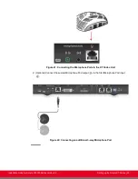


3. Insert the three connectors of the camera cable (3 connectors on one side, 2 connectors on
the other side) to the sockets on the back of the camera, as shown in
cables to the back of the camera
on page 48:
• The DVI connector to the
DVI
socket
• The 8-pin connector to the
IN RS232C
socket
• The power connector to the
DC IN 12V
socket
Figure 34: Connecting cables to the back of the camera
4. Attach the two connectors on the other end of the camera cable as shown in
35: Connecting cables to the Scopia XT Camera Switch
a. The HDMI connector to the HDMI socket labeled
1
on the Scopia XT Camera Switch.
b. The connector for power and serial control to the
horizontal socket on the XT
Codec Unit.
Installation Guide for Scopia XT5000 Series Version 3.2
Setting up the Scopia XT Series | 55


