


Caution:
Failure to remove the camera stabilizing cartons before connecting the camera can cause
damage to the system.
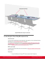
3. Insert these connectors on the camera cable to the ports on the back of the camera, as
Figure 26: Connecting cables to the back of the camera
• The DVI connector to the DVI socket
• The 8-pin connector to the IN (RS232C) socket
• The power connector to the DC IN 12V socket
Figure 26: Connecting cables to the back of the camera
4. Check that the System Select switch on back panel of the camera is set to 7:
Figure 27: Checking the System Select switch
Caution:
To adjust the switch, you must first turn the camera off. Adjust it using a slotted 2.5 mm
screwdriver.
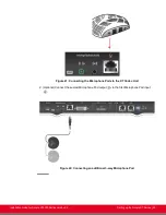
5. Insert the two connectors on the camera cable to the ports on the XT Codec Unit, as shown
in
Figure 28: Connecting the cables to the XT Codec Unit
on page 49:
• The HDMI connector to the vertical socket
• The power connector to the horizontal socket
Installation Guide for Scopia XT5000 Series Version 3.2
Setting up the Scopia XT Series | 48


