Section VI - Servicing
86
Quincy Compressor-QSI
®
Shaft Seal
Compressor shaft seals are wear items that may eventu-
ally have to be replaced. Special tools and a complete
understanding of the installation procedure are required
for a successful seal replacement. Ask your Quincy
distributor for complete illustrated instructions (avail-
able as a Service Alert) at the time you order the seal and
special tools, if you decide to replace the seal yourself.
If your distributor does not have a copy of these instruc-
tions, they can be ordered from Quincy Compressor at no
charge.
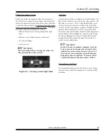
QSI compressors incorporate a fluid scavenge system to
complement the use of a triple lip seal assembly. Any
complaint of shaft seal leakage requires that the scavenge
system be inspected for proper operation prior to the
replacement of the shaft seal. Proper inspection consists
of the following:
•
Assure that the scavenge line itself is not plugged.
•
Inspect the performance of the scavenge line check
valve by removing the fitting located at the bottom
of the motor adapter. Remove the check ball and in
-
spect for wear. If the check valve is stuck open, fluid
can backflush from the airend into the seal cavity and
appear as a leak. If the check valve is stuck closed
the seal cavity will not scavenge. Replace if neces
-
sary.
•
Remove the coupling guards and coupling halves
•
Remove the drive coupling hub and key from the
compressor shaft.
•
Remove the drive motor.
•
Remove the four bolts securing the seal adapter to
the suction housing.
•
Insert two of the seal adapter retaining bolts into the
seal adapter jack holes and turn clockwise (pushing
the seal adapter away from the suction housing).
•
After the seal adapter outer o-ring has cleared the
seal adapter bore, remove the adapter for inspection.
•
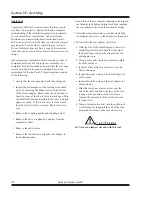
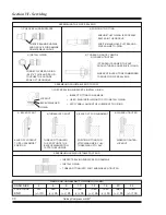
Disassemble the seal adapter as follows:
a. With the face of the seal adapter up, insert two
small, flat screwdrivers under the outer lip of
the fluid slinger and pop the slinger from the
seal adapter bore.
b. Using a brass drift, tap the shaft seal assembly
from the seal bore.
c. Inspect both seal lips for excessive wear, lip
flaws or damage.
d. Inspect the outer o-ring on the fluid slinger for
cuts or nicks.
e. Inspect the outer o-ring on the seal adapter for
cuts and nicks.
f. Slide the wear sleeve removal tool over the
end of the shaft and allow the jaws of the tool
to snap on the backside of the wear sleeve.
Tighten the outer shell of the tool down over
the inner jaws.
g. Using a ratchet and socket, turn the puller jack
screw clockwise in against the end of the com-
pressor shaft to remove the seal wear sleeve.
CAUTION!
Do Not use an impact wrench with this tool.
Содержание QSI Series
Страница 2: ......
Страница 7: ...Section I General Quincy Compressor QSI 5 MODEL IDENTIFICATION...
Страница 62: ...Section IV Operating Procedures 60 Quincy Compressor QSI 1 Week Timer 2 Remaining Running Time...
Страница 79: ...Section IV Operating Procedures Quincy Compressor QSI 77...
Страница 140: ...Table of Contents Quincy Compressor QSI...

