Section III - Installation
Quincy Compressor-QSI
®
15
Manual Vent and Shutoff Valve
Install a manual valve to vent the compressor and the
compressor discharge line to atmosphere. If the air
receiver tank services a single compressor, the manual
valve can be installed in the receiver. When a manual
shut-off valve (block valve) is used, a manual valve
should be installed upstream from the valve, and a pres-
sure relief valve installed upstream from the manual vent
valve. These valves are to be designed and installed to
permit maintenance to be performed in a safe manner.
Never substitute a check valve for a manual shut-off
valve (block valve) if the purpose is to isolate the com-
pressor from a system for servicing.
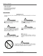
WARNING!
Removal or painting over safety labels will result
in uninformed conditions. This could result in
personal injury or property damage. Warning
signs and labels shall be provided with enough
light to read, conspicuously located and main-
tained for legibility. Do not remove any warning,
caution or instructional material attached.
Water and Sewer Facilities at the Installation Site
(Water-cooled models only)
Make sure the water supply is connected and open. Pip
-
ing supplied by the user should be at least equal to the
connections provided on the compressor. Sewer facilities
should be readily accessible to the installation site and
meet all the requirements of local sewer codes, plus those
of the compressor. Make sure water inlet and discharge
connections are correct.
NOTICE!
The water temperature regulating valve is located
in the discharge water line.
Clean air is essential for your Quincy QSI compressor.
Always select a source providing the cleanest air pos-
sible. When an outside air source is used, keep all piping
as short and direct as possible. Use vibration isolators
and support all piping correctly. Piping size should be
at least as large as the inlet valve opening and increased
several sizes for extremely long piping runs. The piping
must be leak free and clean after fabrication.
WARNING!
Relieve compressor and system air pressure by
opening the appropriate manual relief valve
prior to servicing. Failure to relieve all system
pressure could result in death or serious injury
and property damage.
Compressor Rotation
Compressor rotation must be checked prior to start-up.
Proper rotation is clockwise (as viewed from the power-
input end). The power-input end of the compressor is
marked with an arrow noting the proper rotation. Oper
-
ating the compressor in incorrect rotation will result in
extreme damage to the compressor and warranty cover-
age will be voided. To check for proper rotation, jog the
starter button, allowing the motor to turn 2 or 3 revolu-
tions. Observe the drive element for correct direction.
If incorrect rotation is observed, lock out power supply,
reverse electrical leads L
1
and L
3
at the motor starter.
Recheck for correct rotation.
Fan Rotation (Air-cooled only)
Check the fan rotation at the same time the compressor
rotation is being checked. Fan airflow should be outward,
that is, pushing the air through the coolers.
Содержание QSI Series
Страница 2: ......
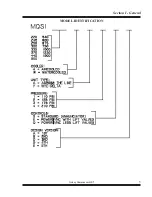
Страница 7: ...Section I General Quincy Compressor QSI 5 MODEL IDENTIFICATION...
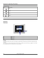
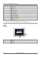
Страница 62: ...Section IV Operating Procedures 60 Quincy Compressor QSI 1 Week Timer 2 Remaining Running Time...
Страница 79: ...Section IV Operating Procedures Quincy Compressor QSI 77...
Страница 140: ...Table of Contents Quincy Compressor QSI...

