

Section VIII - Service Adjustments
Quincy Compressor-QSI
®
107
• Differential Pilot Valve
• Pressure Switch
• Water Temperature Regulating Valve
(Water-cooled units Only)
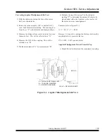
• Drive Coupling Alignment
Differential Pilot Valve
WARNING!
Never adjust the pressure higher than the factory
setting. Death or serious injury and compressor
or property damage could result.
Open a manual vent valve to allow the compressor to
exhaust air to the outside and start the unit. By manual
regulation, slowly close the valve, allowing the unit to
build air pressure to the desired modulation point and
hold (110 PSIG standard). Adjust the screw on the bot
-
tom of the differential pilot valve so that a slight stream
of air can be felt coming from the orifice adjacent to the
adjustment screw.
When this air is felt, air is beginning to pass through the
pilot valve to the air cylinder on the inlet valve, causing
the valve to modulate toward its closed position, thereby
reducing the volume of air being compressed.
To raise the pressure, turn the adjusting screw in (clock-
wise). To lower the pressure, turn the screw out (counter
clockwise). Maximum full load pressure is 110 PSIG
for standard QSI units. Minimum full load pressure with
modulation and standard controls is 75 PSIG.
Pressure Switch
The pressure switch determines what pressure the com-
pressor will load and unload. Standard factory settings
are 110 PSIG cut-in, 125 cut-out. If a lower setting is
desired, adjust the differential pilot valve first and set the
pressure switch cut-out point to 15 PSIG over the desired
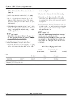
full load pressure. The range adjustment is made by
turning the screw clockwise to increase the cut-in/cut out
pressure.
Water Temperature Regulating Valve
(Water-cooled units Only)
The water temperature regulating valve senses fluid tem
-
perature and opens or closes, regulating water flow from
the unit. It is factory set to maintain 180°F discharge
temperature. Due to different incoming water tempera
-
tures and/or pressures at each location valve adjustment
should be checked during start-up to maintain 180°F
discharge temperature. To increase fluid temperature,
decrease water flow by turning the adjustment screw
clockwise. To decrease fluid temperature, increase water
flow by turning the adjustment screw counter clockwise.
Содержание QSI Series
Страница 2: ......
Страница 7: ...Section I General Quincy Compressor QSI 5 MODEL IDENTIFICATION...
Страница 62: ...Section IV Operating Procedures 60 Quincy Compressor QSI 1 Week Timer 2 Remaining Running Time...
Страница 79: ...Section IV Operating Procedures Quincy Compressor QSI 77...
Страница 140: ...Table of Contents Quincy Compressor QSI...