Publication No. 5106227
12
MAX0041B
135˚
Bend
Ø60
Once the Terminal is
fitted the Head MUST
be pivoted to the
horizontal position
500
74
184
500
Flue
Air
Extension
Mini Terminal (sited in loft)
Support Bracket
Support
Bracket
Roof Tiles
Air Pipe
Flue Pipe
Flue Duct
1.5m min
to
12m max
135˚
Bend
Warning
Note that the length
of the Air Inlet Pipe
MUST not be less
than
0.75 x length
of the Flue Pipe
Pitched Roof Terminal
(25˚- 45˚)
600 mm
min
apart
2 Pitched Roof Terminals
can be used
Pitched Roof
Terminal
(135˚ elbow fitted)
Twin Flue with Pitched Roof Terminal
Used in conjunction with the standard 60 mm diameter
twin pipe flue system, the Powermax Pitched Roof
Terminal (Part No. 5106164) provides an unobtrusive
alternative where horizontal mini terminals are not
practical. This terminal is supplied with a 0.5 m x 0.5 m
universal lead slate; thus it is suitable for use with tiles
and slate roofs with pitch angles of 25° to 45° (above
the horizontal).
The Pitched Roof Terminal must be ordered separately.
It is recommend that, where space and visual
considerations permit, a second similar terminal should
be used for the air supply, especially when the roof
pitch is less than 30°. As an alternative, combustion air
can be taken from a fully ventilated, unoccupied, roof
space providing the minimum free area of the vents is
no less than 234 cm2. Additional requirements are that
the air inlet pipe must not be less than 0.75 x length of
the flue pipe and the intake must be at least 300 mm
above the highest level of the ceiling insulation.
The Pipework Kit (Part No. 5106259) for the Pitched
Roof Terminal is based on a nominal 4.5 m of twin flue.
This allows, for example, up to 5 m of flue pipe between
boiler and flue terminal; plus up to 4 m of air pipe
between boiler and air terminal. The flue pipe must not
exceed 12 m; in which case the air pipe must not be
less than 9 m. The minimum length of flue pipe is 1.5 m
and the overall length is also governed by the number
of bends used - see calculation method on Page 15.
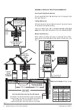
The components supplied with this kit are intended for
a typical application requiring 4.0 m to 4.5 m of air inlet
pipe with 2 bends plus 4.5 m to 5.0 m of flue pipe with
2 bends - See Fig. 16. Other configurations may be
used but a ‘horizontal’ run in the flue pipe should not
exceed 2 m and must not be allowed to dip, i.e. fall
below the horizontal and must always rise towards the
terminal. Any flue pipe accessible to occupiers of the
dwelling must be covered with protective ducts.
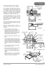
Fixing Pitched Roof Flashing
1. Place terminal flashing in position ensuring the
upwards edge of lead flashing correctly underlaps
the previous course.
Note:
Additional sarking may
be required - see recommendation in BRE Defect
Action Sheet 10 - November 1982 - Pitched Roof
Sarking Felt Underlay Watertightness.
2. Fix any secondary batten needed to support
terminal and reinforce any previously cut battens.
3. Cut slates or tiles to achieve the 290 mm vertical x
220 mm horizontal opening for the upstand of the
terminal. Re-tile roof and dress lead flashing over
bottom course.
4. Fix support bracket so as to secure the flue pipe
near the terminal.
Fig. 15
Fig. 16
Maximum & Minimum Lengths of Air/Flue Pipes


