


Publication No. 5106227
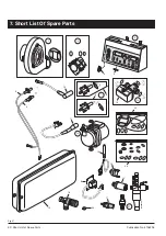
4
M
G
G
H
F
L
G
A
A
F
J
K,N
D
E
J
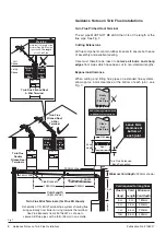
Likely flue positions requiring
a flue terminal guard
C
Q
A
G
K,N
G
P
S
R
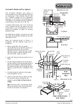
Concentric Horizontal Terminal Flue Kit
Adaptor
Box Assy.
Concentric Elbow
Concentric Terminal
Options for Concentric Flue
1.0 m Concentric Extension
Part No. 5106272
0.5 m Concentric Extension
Part No. 5106271
0.25 m Concentric Extension
Part No. 5106270
Part No. 5106273
Maximum Flue Length 2.5 m
Part No. 5106217
Terminal
Guard
Foam Seal
(included as part of assy)
Wall
Plate
Wall Plate
Screws (2 off)
Wall
Plugs
(2 off)
Elbow to Terminal
Securing Screw
Adaptor to Case
Securing
Screws (4 off)
Flue
Air
Flue Stub Pipe
Elbow
Securing
Screw
MAX0028B
CH
CH
HW
HW
+
SEL
SEL
SEL
SEL
-
PROG
PROG
PROG
PROG
-
BURNER
BURNER
LOCK OUT
LOCK OUT
RESET
RESET
POWER
POWER
MAINS ON
MAINS ON
C.H. ADVANCE
C.H. ADVANCE
+
H.W. TEMP
H.W. TEMP
215
2˚
165 Approx.
Position for Rear Flue Hole
1110 (85 Litre)
1270 (115 Litre)
1470 (150 Litre)
Concentric Elbow 90˚
Part No. 5106158 (1 max.)
Concentric Elbow 135˚
Part No. 5107645 (2 max.)
(additional to Adaptor Box Elbow)
Fanned Draught Balanced Flue
A
Directly below an opening, air brick,
opening window etc.
B
Above an opening, air brick, opening window, etc.
C
Horizontally to an opening, air brick,
opening window etc.
D
Below a gutter, or sanitary pipework
E
Below the eaves
F
Below a balcony or carport roof
G
Above ground, roof or balcony level
H
From vertical drain/soil pipe work
J
From an internal or external corner
K
From a surface facing a terminal
L
Vertically from a terminal on the same wall
M
Horizontally from a terminal on the same wall
N
From a terminal facing the terminal
P
From an opening in a
carport (e.g. door, windows)
into the
building
Q
From adjacent wall to flue (vertical only)
R
From internal corner to flue (vertical only)
S
Below eaves or balcony (vertical only)
Horizontal
Terminal Position with Minimum Distance (mm)
Note:
The distance from a fanned draught appliance terminal installed
parallel to a boundary may not be less than 300 mm in accordance with
the diagram opposite.
300
300
300
75
200
200
300
150
300
600
1500
300
1200
1200
210
230
600
Top View
Top
View
Concentric
Terminal
Assembly
Rear
Concentric
Flue
Side Concentric
Flue
300 min.
300 min.
MAX0027A
Top View
Mini Terminal Assembly
Property
Boundary
Line
Flue
Air
Property
Boundary Line
High Level
Side Twin Flue
300 min.
300 min.
Fig. 3
Fig. 4
Flueing


