Publication No. 5106226
25
Commissioning
3.1 Commission the Boiler
Important
- An automatic air vent is built into the pump
and the cap on the air bleed valve should be closed after
air has been removed from the system.
Flush the System
The system must be flushed in accordance with BS
7593 and the flushing agent manufacturers instructions,
further guidance can be obtained from BS 5449 Section
5.
Use the manual air vent connection on top of the heat
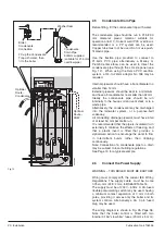
exchanger to add inhibitor - See Fig. 16.
Warning: Do not attempt to start this boiler unless
the primary circuit has been filled with water.
Preliminary Electrical System Checks
These checks must be carried out prior to attempting to
start the boiler. They are, Earth Continuity, Short Circuit,
Polarity & Resistance to Earth.
Sealed Primary System
1. With no water pressure on the system, check and if
necessary adjust expansion vessel pressure to
approx. 1.0 to 1.2 bar (15 to 16 psi).
Note:
Vessel pressure cannot be accurately set with
water pressure in system.
2. Attach a length of hose to the outlet of the manual
vent so that a copious volume of air water mix can
be discharged. Open vent using radiator key.
3. Loosen cap on automatic air vent on pump. Check
that filling loop is connected.
4. Open stopvalves (including filling loop) and fill
system with water. Allow water to continue flowing
from the manual air vent until air is no longer
discharged.
5. Close manual vent and, using the gauge on the
lower pipework, set the system pressure to approx.
1.5 bar.
6. Open one or more hot water taps to ensure the
cylinder is full of water and all air has been
expelled.
7. Thoroughly check water connections on boiler and
inspect radiator valves, unions, etc. for leaks.
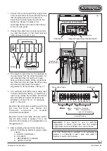
8. Switch on mains electricity supply. Check that
integral programmer is switched on and set so that
either/both CH and HW channels (and CH
thermostat) are calling for heat, (green neons on).
Note:
If remote programmer is being used, the
integral programmer should be disabled by moving
slider switch to left.
9. Check that pump starts immediately (free spindle if
it appears to be sticking). Air should be expelled
from auto air vent and the control display will warn
if system pressure falls below 0.5 bar.
Top up if required. Loosen bleed screw for pump
spindle to remove air and re-tighten.
10.Use the programmer CH and HW buttons to
alternately select central heating and hot water.
Observe that indicator on diverter valve moves
forward (hot water) and back (central heating).
Check that air is expelled from both circuits.
11. Consult the diagnostic codes on Page 39 to
check that control display shows a normal or
indicative code, switch off.
12.The whole of the gas installation must be checked
for soundness and purged in accordance with, in
GB BS 6891 and in IE I.S. 813 “Domestic Gas
Installations”. Loosen screw in gas valve inlet
pressure test point and attach a suitable gauge to
monitor inlet gas pressures. Turn on gas supply at
meter and turn the service gascock on (indicated
by screwdriver slot being in-line – see Fig. 10,
Page 18.
Unvented Domestic Hot Water System
1. With no water pressure on the system, check and
if necessary adjust the secondary expansion
vessel pressure to approx. 2.5 to 2.8 bar (36 to 40
psi).
Note:
Vessel pressure can not be accurately
set with water pressure in system.
2. Open one or more hot water taps.
3. Turn on mains water supply and observe air free
water issuing from tap(s)
4. Close tap(s) and check mains water pipework for
leaks
5. Check that all factory-made plumbing connections
are tight and leak free (and have not loosened in
transit).
6. Manually operate both the Temperature &
Pressure Relief Valve and the secondary pressure
relief valve and ensure that the discharge from
these valves emerges safely. Close them again
with a “snap” action.
Guideline times for the initial heat-up and recovery
for a nominal 50 °C temperature rise (e.g. 15 °C -
65 °C) within the store are:
Unit
Heat-up
Recovery*
85 Litre
18 min.
15 min.
115 Litre
22 min.
18 min.
150 Litre
30 min.
23 min.
* From previous draw-off of 70% of volume.
Starting (Lighting) the Boiler
1. Switch electricity supply on at the isolating switch
and switch the boiler on (‘I’ position on On/Off
switch).
2. Move the boiler on-off switch to the ‘I’ (on) position.
Note that displays are visible in both windows of the
control panel.


