


Publication No. 5106226
16
MAX0021B
Outline of base plate
Outline of front panels
Double arrows are from rear of boiler
70
43
119
122
35
60
54
512
514
536
560
572
544
507
DHW
TPRV
Discharge
Cold
Feed
Gas
Condensate
39
567
Dimensions are approximate
All pipes are 22mm
C/H Flow
Alternate
C/H Flow or
Condensate
Outline of insulation
46
C/H Return
550 Overall
600 o
v
er
all
Installation Requirements
2. Installation
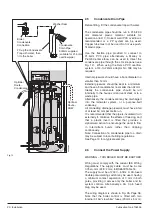
2.1
Install the boiler
Before starting an installation, check that the correct flue
kit and correct capacity cylinder have been supplied.
Important: When soldering plumbing fittings, do not
allow flame from blowtorch to come into contact with
the insulating foam or other non-metallic parts.
Guidance on where to locate the boiler is given in Sections
1.3 and 1.5.
In some instances it will be advantageous
to pre-plumb pipework or to pre-fix terminal, air/flue
pipes and duct
.
1. Remove top and front panels (see Page 3) and
carefully set aside.
2. Determine boiler final position. The cutaway in the
cylinder base allows pipework to be brought up from
below floor level. Use the dimensions below or the
template on the reverse of the Installation Guide to pre-
drill any holes. Pipes must not obstruct service access
to the immersion heater (if fitted) or to the condensate
trap.
3. Move boiler into position. The need to move as Top and
Bottom sections or as a complete assembly will
depend on the individual installation. The Top has 4
downward facing dowel pins which provide accurate
location on to the cylinder. Take care to avoid trapping
hands and fingers during assembly.
4.
Apply sealant to cone faces
of both 22mm Union
Nuts (see Fig. 10). Remove cardboard pipework
support. Attach the 15mm x 90° branch pipe joining the
two relief valves/tundish.
5. Release DHW temperature sensor and un-roll cable.
Route cable behind cylinder pipes and push sensor
fully home (approx. 310mm - 12”) into the pocket in the
cylinder.
6. Remove small knock-outs as required either side of
casing for plumbing access. The handholds in the side
panels can also be used. Further access holes allow
the condensate to be routed via the LH panel and the
DHW to be plumbed via the RH panel.
2.2
Connect the Flue System
1. Unless already fitted, install the flue system as shown
in the Installation Instructions supplied with the flue kit.
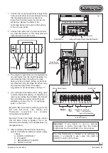
2.3
Connect the Gas Supply
1. Ensure that the gas supply is isolated.
2. The gas connection to the boiler is 22 mm.
Refer to Section 1.1 for information on the required gas
supply.
Do not turn the gas supply on at this stage.
Fig. 9
MAX0023C
22mm Gas
Connection
-
+
PROG
SEL
PROG
SEL
-
C.H. ADVANCE
H.W. TEMP
RESET
BURNER
LOCK OUT
MAINS ON
POWER
+
RWC
This Appliance
Must Be Ear
thed
N
L
N
F HW HW CH CH
T
T
R
L
L
R
R
L
R
2
L
2
Gas
Cock
(0pen)
Fig. 8


