


Publication No. 5106226
35
Powermax
-
+
SEL
SEL
-
+
MAIN
S ON
POW
ER
CH
HW
PRO
G
PROG
C.H. ADVA
NCE
H.W. TE
MP
RESE
T
BUR
NER
LOC
K OU
T
Side View
of
Heat
Exchanger
Heat
Exchanger
Heat Exchanger
bottom of case
To remove
Heat Exchanger
swing bottom forward
Condensate Pipe
(not supplied
with Heat Exchanger)
Condensate
Transfer
Pipe
Condensate Trap
Flue
Diecasting
'O' Rings/Seals Kit
Gas (Part No. 5106295)
'O' Rings/Seals Kit
Water (Part No. 5106296)
Remove bottom
Clip from the Saddle
Burner
Assembly
removed
Saddle
Disconnect Flow
& Return Pipes
Flow &
Return
Pipe
Securing
Clips
Saddle
Flue
Diecasting
Flue Seal
Grommet
Disconnect
HE
from RH
Support
Bracket
(which is
part of case)
Disconnect
H. Exchanger
from LH
Support Brackets
MAX0025B
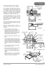
4.12
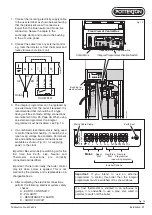
Heat Exchanger
Note:
Replacing the heat exchanger
involves disconnecting the appliance from
the flue and air pipes. It is essential that the
flue system is fully reinstated and tested so
we recommend that the appropriate
replacement flue pipe and fittings be
obtained before starting this work. The slip
fitting Part No.5106807 will be helpful in
reinstating extended twin pipe flue systems.
Re-assemble all parts in reverse order.
1. Perform 4.1 General Access.
2. Check that the boiler primary system is
isolated from the mains water supply.
Release pressure from the primary
system and drain down.
3. Remove expansion vessel, pump, gas
valve, fan/venturi, diverter valve and heat
exchanger door (complete with burner) all
as detailed in previous sections. Remove
flow and return pipework from the push-fit
connections on RH manifold of heat
exchanger. Retain securing clips for re-
use.
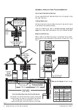
4. Disengage air inlet duct from elbow on top
RH side of boiler and set aside. Unscrew
3 c/sunk screws and remove air inlet
elbow.
5. Disconnect wiring from temperature
sensors and overheat thermostat.
Carefully remove HT lead from spark
generator.
6. Disconnect flue pipe. Remove “hidden”
M6 nut - see Fig. 24, at RH rear of heat
exchanger and remove two M6 flanged
set screws securing the LH suspension
bracket. Support weight of heat
exchanger before removing the clip and
saddle beneath.
7. Lift heat exchanger vertically about 19mm
(3/4”) to disengage condensate spigot
from its socket in the base panel; then tilt
forward from the bottom to remove.
Fig. 24
Replacement of Parts


