


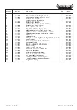


Publication No. 5106226
31
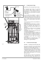
4.5
Air/Gas Valve/Injector/Fan
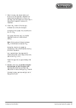
Re-assemble all parts in reverse order.
1. Perform 4.1 General Access.
2. Isolate the gas cock.
3.
Air/Gas Valve
Important: DO NOT attempt to replace
the air/gas valve unless a combustion
analyser is available. See Page 42 for
setup procedure.
Remove the screws securing the gas pipe
securing plate to the air/gas valve.
Remove the screw securing the injector to
the venturi body.
Disconnect all electrical connections to
the valve and the air pressure sensing
tube.
Pull the air/gas valve complete with
injector forward and away from the venturi
body.
4.
Injector
Remove the screws securing the plate to
the air/gas valve and pull out the injector.
On re-assembly, leave the securing plate
slightly loose so the injector can be turned
to
allow the flat to line up with the flat
on the inside of the venturi
body.
Use an 8 mm A/F spanner to ‘nip’ the
screws when in position.
5.
Fan
Disconnect the electrical connections at
the fan.
Remove the 3 bolts securing the fan to the
venturi and the 4 screws and nuts
securing the fan to the burner.
Carefully lift the fan out and away from the
boiler.
Be careful not to lose the large ‘O’ ring
between the fan and venturi.
Inspect and if necessary replace gasket
behind the fan outlet flange.
Transfer large ‘O’ ring on fan intake to new
fan.
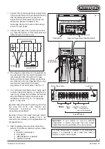
Powermax
-
+
SEL
SEL
-
+
MAIN
S ON
POW
ER
CH
HW
PRO
G
PROG
C.H. A
DVAN
CE
H.W. TE
MP
RESE
T
BUR
NER
LOC
K O
UT
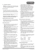
Air/Gas
Valve
Flue Gas
Test Point
Air
Manifold
Gas Pipe
Venturi
Fan
Gas
Pipe
Gas Pipe
Securing Plate
Injector
Fan
'O' Ring
Air/Gas
Valve
Venturi
Connector
Air
Manifold
Venturi
Fan Securing
Screws
Fan
Mounting Gasket
Fan
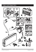
Air/Gas Ratio Valve
Top View of Air/Gas Ratio Valve
Inlet Pressure Test Point
Outlet Pressure Test Point
Air Signal
Connection
Offset
Adjustment
Injector Securing
Plate & Screws (3 off)
MAX0018C
Injector
Venturi-Injector
Location Flat
'O'
Rings
Injector Locking
Grub Screw
Gas Cock
CH Flow
Fig. 20
Replacement of Parts


