


Publication No. 5106226
28
1
4
3
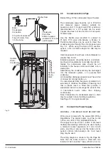
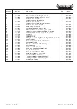
Uunscrew Top Panel
and lift away
Pull forward Front
Panel at the bottom
and lift off
Unscrew Upper Panel at
the bottom and pull away
Pull forward Bottom Panel
General Access
2
Retaining Screws - Upper Panel
Remove Front
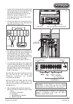
Engine
Box Cover
Access Panel
for Automatic
Air Vent - Bleed
Powermax
-
+
SEL
SEL
-
+
MAINS ON
POW
ER
CH
HW
PRO
G
PROG
C.H. A
DVAN
CE
H.W. T
EMP
RESE
T
BUR
NER
LOC
K O
UT
Pull away
Securing
Clip
Pump Body
Pull out
Auto Air
Vent
Auto Air
Vent Parts
MAX0004C
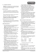
Powermax
Front
Fascia
Removal
Front
Fascia
Lift Off
Front Fascia
Location Peg
Remove Front Fascia Securing Screws
Side Support
Internal Access
Retaining Screws - Top Panel
Retaining
Screws -
Top Panel
4.1
General Access
Warning
:
Before attempting to remove any
component from the boiler first disconnect the mains
electricity supply by removing the plug from the wall
socket or by switching off the boiler at the external
isolating switch.
Warning
: The fan operating voltage is 325V d.c. Take
appropriate precautions. Allow at least 40 seconds to
elapse before handling the PCB within the boiler
control assembly.
Important:
After removal or replacement of any gas
carrying component a test for gas soundness must
be made and functional check of the controls carried
out.
Important
: Any 'O' rings, seals, gaskets or washers
disturbed during replacement of parts must be
visually inspected and replaced if worn or damaged.
Re-assemble all parts in reverse order.
1. Follow stages 1 - 4 (opposite) to remove the
outer panels.
Internal Access
2. Remove the screws securing the top engine
box cover and lift the cover away from the
boiler.
3. Remove the screws securing the front engine
box cover and lift the cover away from the
boiler.
4.2
Automatic Air Vent
Re-assemble all parts in reverse order.
1. Perform 4.1 General Access, remove the
access panel rather than the front engine box
cover.
2. Pull away the securing clip and lift out the air
vent parts as shown.
Fig. 17
Replacement of Parts


