


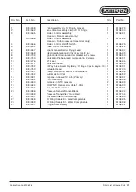


Publication No. 5106226
33
TEMP
MAINS
ON
BURNE
R
LOCK O
UT
RESET
ADVAN
CE
PROG
STEP
SEL
SEL
Powermax
Lift Off
Control Box
Fuse
(3.15A
Slow Blow)
Boiler Control
Securing
Screws
Boiler
Control
Boiler Control
Support
Plate
Disconnect
Electrical
Connectors
Remove Cover
Plate
MAX0019C
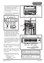
Front View of Boiler Control
Top
Electrical
Connectors
High Voltage Connectors
Low Voltage Connectors
J5
J12 J8
JP2
J7
J4
J11 J13
J15
J16
Earth
Pump
Diverter
Valve
Pressure
Sensor
Flow/Return
Sensors
Ionisation Probe
Fan
DHW Temp
Diagnostic
Port
O/heat 'Stat
& Gas Valve
J4 Spare
J10
Boiler
Control
Support
Plate
Powermax
Remove Front Fascia
Front Fascia
Lift Off
Front Fascia
Remove Front Fascia
Securing Screws
Side Support
Spark
Generator
Location Peg
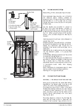
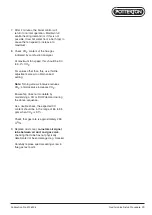
4.8
Boiler Control Assembly
Warning
: The fan operating voltage is 325V
d.c. Take appropriate precautions. Allow at
least 40 seconds to elapse before handling
the PCB within the boiler control assembly.
Re-assemble all parts in reverse order.
1. Perform 4.1 General Access.
2. Isolate the electricity supply to the boiler.
3. Remove wiring cover plate.
4. Remove securing screws from fascia,
note how it fits and with great care,
remove it from the boiler.
5. Disconnect all electrical connectors at the
control box. On re-assembly, connect as
shown on the wiring diagram.
6. Remove the two screws securing the
control box to the support plate, note how
it fits and
carefully remove
it from the
boiler.
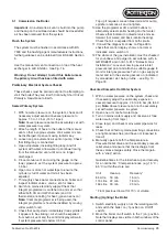
Fuse:
This is located on the control board
as shown opposite.
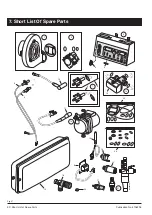
Fig. 22
Replacement of Parts


