Publication No. 5106226
32
Powermax
-
-
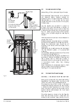
CH Flow
Heat
Exchanger
Burner
Fan
4mm
Spark
Gap
(between
wires)
When cleaning burner
DO NOT unscrew from
Heat Exchanger Door
Heat
Exchanger
Door
Burner
MAX0017D
Spark
Generator
Spark Generator
Supply Cable
& Earth to
Control Box
Ionisation
Probe to
Control Box
Ionisation
Probe
Fan
Support
Electrode Earth Lead
Electrode
Lead
Securing
Screws
Electrode
Earth
Lead
Earth
Lead
Supply Cable
Ignition Electode
Heat Exchanger
Door &
Securing Nuts
Heat Exchanger
Spark
Generator
Alternative
Ignition Electode
Gas Cock
4.6
Spark Generator/Ignition
Electrode
Re-assemble all parts in reverse order.
1. Perform 4.1 General Access.
2. Isolate the gas cock.
3. Spark Generator
Carefully disconnect the electrode lead
from the spark generator.
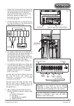
Remove supply cable from top of boiler
control - see Fig. 22.
Remove the screws securing the spark
generator to its bracket (ensure earth wire
is re-connected on re-assembly).
3.
Ignition Electrode
Carefully disconnect the earth lead at the
electrode.
Remove the screws securing the
electrode to the heat exchanger.
Carefully remove the electrode from the
heat exchanger.
On re-assembly check that the spark gap
between the tips is 3.5 - 4.0 mm.
3.
Ionisation Probe
Carefully disconnect the ionisation probe
lead at the boiler control.
Remove the screws securing the probe to
the heat exchanger.
Carefully remove the probe from the heat
exchanger.
4.7
Burner
Re-assemble all parts in reverse order.
1. Perform 4.1 General Access.
2. Isolate the gas cock.
3. Remove the Fan (Section 4.5, Air/Gas
Valve/Injector/Fan).
4. Disconnect the ionisation probe,
electrode lead and earth lead.
5. Remove the nuts securing the heat
exchanger door to the heat exchanger.
6. Carefully remove the door complete with
burner from the heat exchanger.
Important:
Do not separate the burner
from the heat exchanger door.
Fig. 21
Replacement of Parts


