


Publication No. 5106227
13
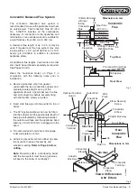
Twin Flue with Horizontal Mini Terminal
The Mini Terminal flue system provides an
unobtrusive arrangement.
Separate 60 mm
diameter air inlet and flue terminal assemblies can
be positioned in different locations on the same wall
subject to similar wind conditions. The mini
terminals are also visually less obtrusive and are
available in a small range of colours to assist with
the sympathetic re-furbishment of older buildings.
The twin flue system allows greater flexibility when
siting the appliance. It offers up to 12 m of flue and
12 m of air pipe, which must be reduced to
accommodate the number of bends for more
difficult applications. Both terminals should be
positioned to minimise the length of the air and flue
pipes. The distance between the terminals must not
be less than 360 mm and no greater than 2 m.
Maximum Flue Length: 12 m flue pipe
12 m air pipe
2 x 92° swept bends
Minimum Flue Length
1 m flue pipe
1 m air pipe
2 x 92° swept bends
All additional flue lengths, flue bends and other kits
should be purchased separately as required. See
Pages 8 and 9.
Read the ‘Guidance Notes’ on Page 2 in conjunction
with the following notes prior to installation.
a. The Powermax HE is a condensing boiler and
the flue system must have a generous fall back
to the appliance (nominally 2°) and be
adequately supported. This will ensure the
correct trouble free disposal of condensate
produced in the flue during normal operation.
b. All flue components contain rubber lip seals to
ensure both ease of assembly and excellent
sealing.
Refer to Page 6 before cutting.
Note:
Damage to the seals could result in
condensate/flue products leakage from the flue
system.
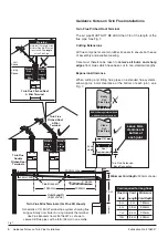
Important: The flue terminal MUST NOT be sited
below the air terminal. See Fig. 17.
Warning:
The flue pipe becomes very hot when
appliance is working. Householders should be
warned not to touch exposed pipe e.g. beyond
protective duct within loft. The flue pipe should be
insulated or ducted if accidental contact is likely.
View
of
Outside
Wall
Fixed Flue
Terminal position
Flue
Possible Air Terminal positions
MAX0036B
Air
Air
Air
Mini Terminal Clearances
Flue
Clearance
Zone
Flue
Air
Air
Air
Air Exclusion
Zone
360mm minimum
centre to centre
Flue Air
2˚ Angle
Flue
Air
Twin Flue Mini
Terminals (Righthand)
MAX0043B
Flue
Air
Minimum
360 mm
centres
apart
Mini Terminal
(Ø60 x 500)
Air Pipe
Flue Pipe
Flue Duct
150˚ Bend
Extension
92˚
Bend
1m min
to
12m max
Twin Flue Mini
Terminals
(Rear)
Fig. 17
Fig. 18
Twin Flue with Horizontal Mini Terminal