English
Electric wire rope winch >BETA< SILVERLINE
04.01.401
technische Änderungen vorbehalten
design changes under reserve
changements techniques sous réserve
Seite / page 25
Overload protection:
Wire rope winches with a load of 1000kg and more
have to be equipped with an overload protection.
The contactor control of winches with a capacity of 1000kg
and more will include the electronic overload protection.
The overload protection operates by means of a load
monitoring device, which is adjusted to 100% up to 110% of
the driving power.
The mounted electronic overload protection works with a start
bridging and do not release the operator to check the carrying
capacity and the charge. Take care that the load does not
interlock during the starting phase.
The overload protection does not operate by constant press-
release in short intervals.
The electronic overload protection is a warning installation and
it is not allowed for regular use to stop at end positions. Use
always path-dependent limit switches to stop at positions.
Take into consideration the rigidity of the complete lifting
installation (inclusive frame etc.) in connection with the max.
overload time (start bridging, brake time, etc...) to determine
the overload factor. The max. overload should not exceed the
upper limits of the carrying capacity of the system. (Take
notice of the valid directives.)
The manufacturer of the entire installation is responsible for
deciding the overload capacity of the system.
The operator is not allowed to change the adjustment of
the load monitoring device.
Limit switch
If limit position cannot safely be overlooked by the operator,
operating limit switches have to be installed.
The limit switches have to be integrated into the circuit in a
functionally correct manner.
Depending on the application, i.e. for cranes etc., additional
emergency limit switches are stipulated. They have to be
designed according to the respective standards and checked.
The manufacturer of the entire installation takes the
responsibility.
With mounted-in limit switches, definitely check function in
connection with the entire installation.
With wrong polarity or wrong connection, the limit switches are
ineffective.
The winches can be equipped with mounted on gear limit
switch.
Attention:
Do not operate the winch until having ad-
justed and connected the limit switches!
Please observe:
–
Depending on design the adjustment precision of the
limit switch is approx. ±50mm. This cut off precision
can only be kept in the first layer.
–
The after running of the winch is approx. 1/100 up to
1/500 of the lifting speed [m/min].
–
In any case, it has to be observed that the elongation
of the rope may change the lift limit positions. The
remaining elongation of the rope up to replacement
state of wear may be approx. 1 %.
–
A regular check of the adjustment/turn-off ways is
necessary.
Adjustment of the gear limit switch
For contact adjustment, remove the cap of the
limit switch. Before adjusting the switching point
assure that the live contact connection are cov-
ered by a protection against accidental touch or
with flat plugs by a receptacle for tabs, and that
touching of the connections is excluded.
The limit switch is provided with individual or block
adjustment.
Individual adjustment
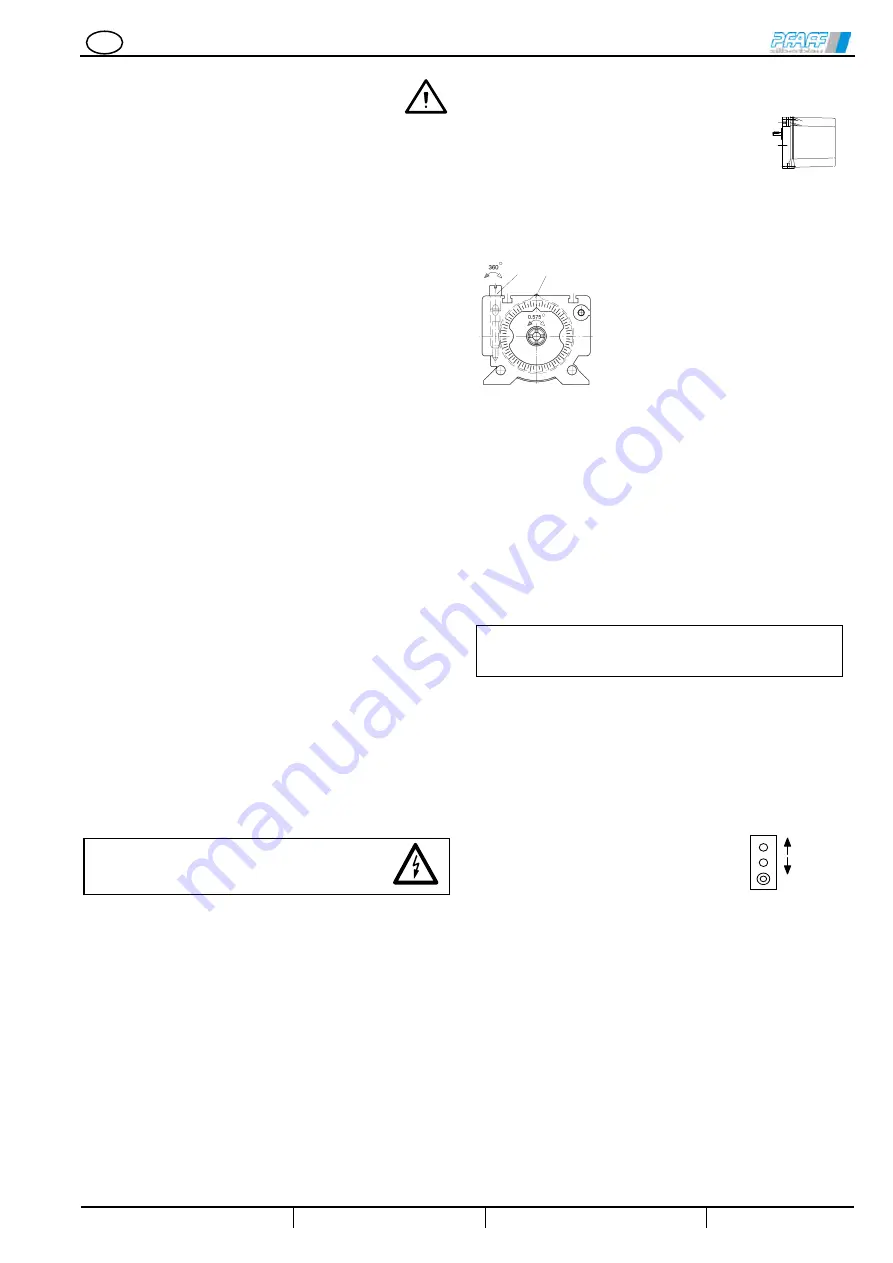
An infinitely adjustable cam disc is
provided for each contact. Independently
from each other, the cam discs (1) can
be set with the white adjusting worm (2).
It is not necessary to loosen any parts for
the adjustment. The worm is self-locked.
The worm can be turned by means of a
screw driver of 10mm or 4mm or by
means of a hexagon socket screw key of
4mm.
When turning the worm by one clockwise revolution 360°, the
cam disc as well is turned clockwise by 2,464° (view to the
rear part, the B-side of the switch).
The standard cam discs are designed to dispose of a max.
useful travel and a max. overtravel. When exceeding the over-
travel, the switch is not damaged. The contact, however, is
opened or closed again.
Block adjustment
With the black adjusting worm (2) the base of all cam discs (1)
can be commonly adjusted. The relatives adjustments of the
individual contacts to each other are not modified. When
turning the black worm clockwise by one revolution, the cam
discs as well are turned clockwise by 0,575°.
If functions provided by the el. control are not
required for operation, the terminals which are not
required have to be by-passed respectively.
Slack rope switch
For guided loads, a safety device must be provided which
switches the winch off in case of slack rope to avoid
falling down of the load.
As option, the electric winch >BETA< SILVERLINE may be
equipped with slack rope switch. For instructions for putting
into operation and adjustment please refer to page 42 & 45.
Operating Elements:
The operating elements (operating
places) have to be installed in such
a way that the entire load distance
can be overlooked from the operator's position.
Push-buttons are to be located in reasonable position.
Protective measures:
Connection, protective measures and safety pre-
cautions have to be effected according to local,
national and international regulations.
Before taking into operation, check:
Ö
correct polarity, turning direction, placement of order de-
vices
Ö
protective conductor system
Ö
insulation resistance
Ö
overload protection adjustment (if existing)
Ö
function
2
1
lifting
lowering
emergency-stop


